LMIC Library Always Does Unwanted Downlink

Note: I have updated this post, due to resolving part of the issue.

I am using the LMIC library by @matthijskooijman to transmit temperature and humidity data from a DHT11 sensor. The microcontroller I am using is a TTGO ESP32 SX1276 without the OLED. For some reason, when I do a transmission, by using the do_send(&sendjob) function, my console shows:

3rd. Downlink (which I have not specified anything for)
2nd. Uplink
1st. Connects

02%20am

Please ignore the additional bytes I am sending. I’m clearing this up at the moment and doing some testing.

These are the downlink details in the application console:

37%20am

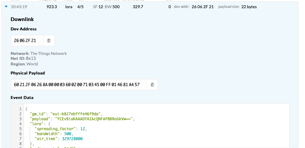
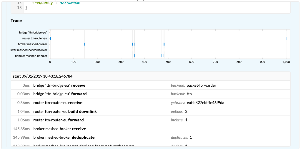
These are the downlink details in the gateway console:

Please note that these details are for a different time point, but seeings all downlinks are blank in the application console, I’m assuming they are the same.
01%20am
25%20am

This means that two transmissions are occurring, one from the node to the gateway and the other way around. In my code, I make the ESP32 deep sleep, which means that the board should only go through that command once. I have specified this in the TX_COMPLETE case.

What I want to occur is for only a single uplink, meaning I want the downlink disabled as this is additional wasted airtime, eating into the maximum number of transmissions I can perform.

But, first would anyone know what is causing these two transmission?

Here is my code:

#include <lmic.h>
#include <hal/hal.h>
#include <SPI.h>
#include <dhtnew.h>

//Here we use pin IO14 of ESP32 to read data
DHTNEW dht(14);

// Temperature
float temp_raw;
float temp_multiplied;
int temp_adjusted;

// Humidity
float humid_raw;
float humid_multiplied;
int humid_adjusted;

// Combined Array
static uint8_t combined_array[4];

// APPEUI needs to be in little endian / least-significant-byte (lsb) format
// This is found by clicking on < > next to "Device EUI" and then the two arrows icon 
static const u1_t PROGMEM APPEUI[8] = {  };
void os_getArtEui (u1_t* buf) {
  memcpy_P(buf, APPEUI, 8);
}

// DEVEUI needs to be in little endian / least-significant-byte (lsb) format
// This is found by clicking on < > next to "Device EUI" and then the two arrows icon 
static const u1_t PROGMEM DEVEUI[8] = {  };
void os_getDevEui (u1_t* buf) {
  memcpy_P(buf, DEVEUI, 8);
}

// APPKEY needs to be in big endian / most significant byte format (msb) format
// This is found by clicking on < > next to "Device EUI"
static const u1_t PROGMEM APPKEY[16] = {  };
void os_getDevKey (u1_t* buf) {
  memcpy_P(buf, APPKEY, 16);
}

static osjob_t sendjob;

// Schedule TX every this many seconds (might become longer due to duty
// cycle limitations)
const unsigned TX_INTERVAL = 5;

// Pin mapping
const lmic_pinmap lmic_pins = {
  .nss = 18,
  .rxtx = LMIC_UNUSED_PIN,
  .rst = 14,
  .dio = {26, 33, 32},
};

void onEvent (ev_t ev) {
  Serial.print(os_getTime());
  Serial.print(": ");
  switch (ev) {
    case EV_SCAN_TIMEOUT:
      Serial.println(F("EV_SCAN_TIMEOUT"));
      break;
    case EV_BEACON_FOUND:
      Serial.println(F("EV_BEACON_FOUND"));
      break;
    case EV_BEACON_MISSED:
      Serial.println(F("EV_BEACON_MISSED"));
      break;
    case EV_BEACON_TRACKED:
      Serial.println(F("EV_BEACON_TRACKED"));
      break;
    case EV_JOINING:
      Serial.println(F("EV_JOINING"));
      break;
    case EV_JOINED:
      Serial.println(F("EV_JOINED"));
      // Disable link check validation (automatically enabled
      // during join, but not supported by TTN at this time)
      LMIC_setLinkCheckMode(0);
      break;
    case EV_RFU1:
      Serial.println(F("EV_RFU1"));
      break;
    case EV_JOIN_FAILED:
      Serial.println(F("EV_JOIN_FAILED"));
      break;
    case EV_REJOIN_FAILED:
      Serial.println(F("EV_REJOIN_FAILED"));
      //break;
      break;
    case EV_TXCOMPLETE:
      Serial.println(F("EV_TXCOMPLETE (includes waiting for RX windows)"));
      if (LMIC.txrxFlags & TXRX_ACK) {
        Serial.println(F("Received ack"));
      }
      if (LMIC.dataLen) {
        Serial.println(F("Received "));
        Serial.println(LMIC.dataLen);
        Serial.println(F(" bytes of payload"));
      }
      //Schedule next transmission
       delay(10);
       esp_deep_sleep(10000000);
       //break;
    case EV_LOST_TSYNC:
      Serial.println(F("EV_LOST_TSYNC"));
      break;
    case EV_RESET:
      Serial.println(F("EV_RESET"));
      break;
    case EV_RXCOMPLETE:
      // Data received in ping slot
      Serial.println(F("EV_RXCOMPLETE"));
      break;
    case EV_LINK_DEAD:
      Serial.println(F("EV_LINK_DEAD"));
      break;
    case EV_LINK_ALIVE:
      Serial.println(F("EV_LINK_ALIVE"));
      break;
    default:
      Serial.println(F("Unknown event"));
      break;
  }
}
void do_send(osjob_t* j) {
  // Check if there is not a current TX/RX job running
  if (LMIC.opmode & OP_TXRXPEND) {
    Serial.println(F("OP_TXRXPEND, not sending"));
  } else {
    // Prepare upstream data transmission at the next possible time
    
    // Temperature
    LMIC_setTxData2(1, combined_array, sizeof(combined_array)+4, 0);
    //FIRST 1 is port number
        
    Serial.println(F("Packet queued"));
  } 
  // Next TX is scheduled after TX_COMPLETE event
}

void setup() {
  Serial.begin(115200);
  
  SPI.begin(5, 19, 27);

  Serial.println("The sensor just started up! #Finallyitsworking!");
  // Call read to get data from sensor
  dht.read();
  
  // Read temperature as Celsius (the default)
  temp_raw = dht.temperature;
  temp_multiplied = temp_raw*10;
  temp_adjusted = int(temp_multiplied);
  
  Serial.print("To show you the sensor is working, this is the temperature: ");
  Serial.print(temp_adjusted/10);
  Serial.println(" *C");  

  // Read humidity as a percentage
  humid_raw = dht.humidity;
  humid_multiplied = humid_raw*10;
  humid_adjusted = int(humid_multiplied);
  
  Serial.print("To show you that the sensor is working, this is the humidity: ");
  Serial.print(humid_adjusted/10);
  Serial.println(" %");  

  // Combining both temperature and humidity arrays, ready for tranmission
  memcpy(&combined_array, &temp_adjusted, sizeof(temp_adjusted));
  memcpy(&combined_array + sizeof(temp_adjusted), &humid_adjusted, sizeof(humid_adjusted));

  // LMIC init
  os_init();

  // Reset the MAC state. Session and pending data transfers will be discarded
  LMIC_reset();
  
  // Start job (sending automatically starts OTAA too)
  do_send(&sendjob);
}

void loop()
{
  os_runloop_once();
}

And here is my console output from the ESP32 waking to deep sleep:

rst:0x5 (DEEPSLEEP_RESET),boot:0x17 (SPI_FAST_FLASH_BOOT)
configsip: 0, SPIWP:0xee
clk_drv:0x00,q_drv:0x00,d_drv:0x00,cs0_drv:0x00,hd_drv:0x00,wp_drv:0x00
mode:DIO, clock div:1
load:0x3fff0018,len:4
load:0x3fff001c,len:952
load:0x40078000,len:6084
load:0x40080000,len:7936
entry 0x40080310
The sensor just started up! #Finallyitsworking!
To show you the sensor is working, this is the temperature: 25 *C
To show you that the sensor is working, this is the humidity: 59 %
Packet queued
4898: EV_JOINING
1146049: EV_JOINED
1431693: EV_TXCOMPLETE (includes waiting for RX windows)
Received ack
ets Jun  8 2016 00:22:57
Check the “history” of downlinks (open them, you may see the reason for them).

I think I’ve sorted the two transmissions. I changed the last 1 to a 0, in this line:

LMIC_setTxData2(1, combined_array, sizeof(combined_array)+4, 1);

To:

LMIC_setTxData2(1, combined_array, sizeof(combined_array)+4, 0);

However, I still am unsure how to stop the downlink.

This way you should have stopped confirmation, that is, downlink. However, if you look at the downlink details in console, you may understand which kind of downlink is.

1 Like

So what’s the situation since you disabled the confirmation?

US915 gets an initial ADR to tell the node about which channels to use:

There are a several moments when an ADR request is scheduled or sent:

  1. The initial ADR Request (for US915 and AU915). This is sent immediately after join and is mainly used to set the channel mask of the device. This one is a bit tricky, because we don’t have enough measurements for setting an accurate data rate. To avoid silencing the device, we use an extra “buffer” of a few dB here. This request is only needed with pre-LoRaWAN 1.1 on our v2 stack. With LoRaWAN 1.1 devices on our v3 stack, we can set the channel mask in the JoinAccept message. ABP devices pre-LoRaWAN 1.1 will only get this message once, if they reset after that, they won’t get the message again; this issue is also solved by LoRaWAN 1.1.

  2. […]

Reading the above (emphasis mine) I’d guess it would not need an uplink first, but then: the node will not be listening after receiving the Join Accept, so TTN can indeed only piggy-back the ADR on a downlink after the first uplink. Like @UdLoRa wrote: click the downlinks to see the details. If you have access to the gateway’s Traffic page in TTN Console, then check that one too. Maybe given the actual payloads we can you more. (Maybe the ADR is in the Join Accept?)

Hi @arjanvanb, I have since updated the post, showing the details of the downlinks. Hopefully this can help you assist me with this issue.

@UdLoRa, I have adjusted the post. This shows the output of the downlink details.

My answer has not changed…

(So, give us the full packet of the downlink as seen in the gateway’s Traffic page, or decipher it yourself using an online decoder. You’re looking for the contents of FCtrl and FOpts.)

1 Like

Using that online decoder here are the values of FCtrl and F0pts, which were decoded by entering the Secret NwkSKey and AppSKey. Note that this was pulled from the gateway console as the application shows the payload as not provided.

FCtrl = 8A
FOpts = 0360020071035500FF01

Below is the complete downlink payload:

Assuming hex-encoded packet
60E01000268A00000360020071035500FF016C29CA5C

Message Type = Data
  PHYPayload = 60E01000268A00000360020071035500FF016C29CA5C

( PHYPayload = MHDR[1] | MACPayload[..] | MIC[4] )
        MHDR = 60
  MACPayload = E01000268A00000360020071035500FF01
         MIC = 6C29CA5C (from packet)
             = 6C29CA5C (expected, assuming 32 bits frame counter with MSB 0000)

( MACPayload = FHDR | FPort | FRMPayload )
        FHDR = E01000268A00000360020071035500FF01
       FPort = 
  FRMPayload = 

      ( FHDR = DevAddr[4] | FCtrl[1] | FCnt[2] | FOpts[0..15] )
     DevAddr = 260010E0 (Big Endian)
       FCtrl = 8A
        FCnt = 0000 (Big Endian)
       FOpts = 0360020071035500FF01

Message Type = Unconfirmed Data Down
   Direction = down
        FCnt = 0 (from packet, 16 bits) 
             = 0 (32 bits, assuming MSB 0x0000)
   FCtrl.ACK = false
   FCtrl.ADR = true

Correct. There is no application payload; this is only a network MAC command.

Hexadecimal 0x8A in FCtrl equals binary 0b10001010, hence indeed indicates it’s ADR (I wonder if that’s needed), and that FOptsLen = 10, so FOpts holds 10 bytes for MAC commands:

Those 10 bytes indeed start with 0x03 are actually two MAC commands, both starting with 0x03, both denoting a LinkADRReq, in which the server is requesting the device to adjust its settings:

See the LoRaWAN 1.0.1 specifications on how to decode the 10 bytes.

For AU915-928, the first 5 bytes, 0x0360020071:

  • 0x03 = LinkADRReq
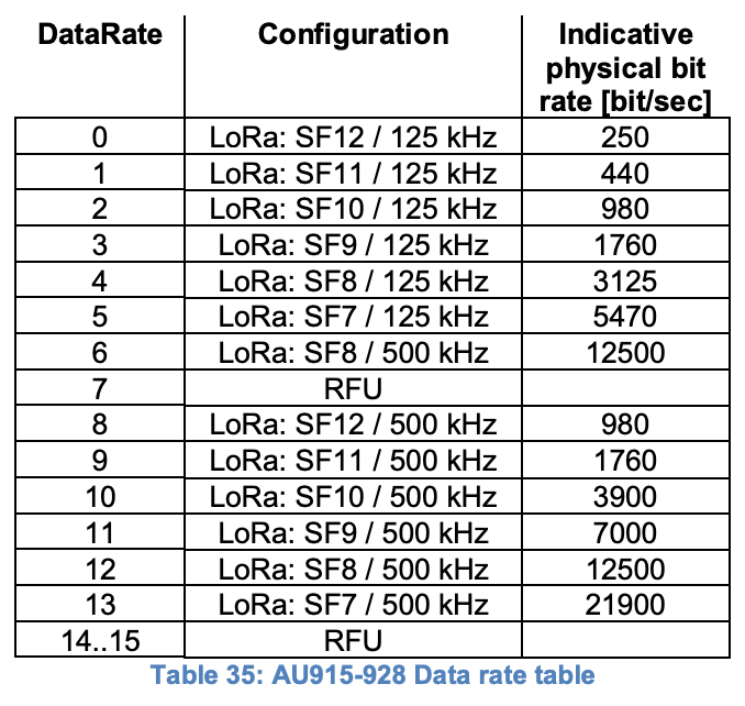
  • 0x60 = DataRate_TXPower: data rate 6 (reserved for future use?); TX power 0 = 30 dBm
  • 0x0200 (LSB) = 0b00000000 00000010 (MSB) = ChMask: index 2
  • 0x71 = 0b01110001, so ChMaskCntl = 0b111: all 125 kHz OFF, and ChMask applies to channels 64 to 71, so index 2 only enables channel 65, being 917.5 - 500 kHz BW at DR4

…and the second part, 0x035500FF01:

  • 0x03 = LinkADRReq
  • 0x55 = DataRate_TXPower: data rate 5 (reserved for future use?); TX power 5 = 20 dBm
  • 0x00FF (LSB) = 0b11111111 00000000 (MSB) = ChMask: index 8 to 15
  • 0x01 = 0b00000001, so ChMaskCntl = 0b000: ChMask applies to channels 0 to 15, so index 8 to 15 enables channels 8 to 15, being 916.8 - 918.2 MHz, 125 kHz BW at DR0 to DR3

This indeed matches the 9 channels that TTN uses for AU915-928. (I’m not 100% sure I got the decoding right; I don’t understand the data rates. I should have used 1.0.2 for the decoding; see subsequent posts.)

The ADR request is needed for AU915 (and US915) because LoRaWAN 1.0.1 does not support these settings to be provided in the Join Accept response. (It does support that for EU868.) For LoRaWAN 1.0.3 and 1.1 this is supported, like the ADR documentation I quoted above already mentioned. I don’t think TTN supports 1.0.3, but it will support LoRaWAN 1.1 as of V3.

So, all as expected, and hopefully your version of LMIC will handle the ADR request. If it does, then the next uplink should include the LinkADRAns MAC command, to tell the server it handled it. So, the second uplink should show some values for FCtrl and FOpts as well.


For an EU868 example, see ADR problems - node of the same type have different ADR behaviour - #11 by arjanvanb.

3 Likes

@arjanvanb AU915 datarates change in 1.0.2rB to DR0-6

2 Likes

Nice, mystery solved!

image

And I guess TTN supports LoRaWAN 1.0.2 then, which still says:

2.5.4 AU915-928 JoinAccept CFList

The AU915-928 LoRaWAN does not support the use of the optional CFlist appended to the JoinAccept message. If the CFlist is not empty it is ignored by the end-device.

Whereas 1.0.3 states it’s actually supported:

2.6.4 AU915-928 JoinAccept CFList

The AU915-928 LoRaWAN supports the use of the optional CFlist appended to the JoinResp message. If the CFlist is not empty then the CFListType field SHALL contain the value one (0x01) to indicate the CFList contains a series of ChMask fields. The ChMask fields are interpreted as […]

1 Like

Okay. Thanks for the clarification. So, just that I understand, is this an expected occurrence due to the device having the initialise and setup ADR because of AU915?

There is an issue with this. Due to the fair access policy, I will infringe on the maximum number of downlinks in no time:

How then do I resolve this problem? On the surface, the downlinks are little more than a nuisance, but mean that I currently would not be able to use these nodes if I wish to follow the rules.

Also, is this the case for all LoRaWAN nodes using AU915, or is this limited to the LMIC library and it’s supported devices? I don’t recall other devices I have testing doing this, but I may be mistaken.

use another platform

Are the TTGOs, not suitable for LoRaWAN deployment then? I’m happy and already intending to transition over to another platform, however I have already invested resources and time into this hardware, meaning I don’t wish to bin what have done so far.

Seeings that quite a few people in the community use them, does that mean that users of these will always be limited to a maximum of 10 uplinks, if they choose to deep sleep, due to the device resetting?

You should only do an OTAA Join when your device unexpectedly has lost its state. During normal operation, it should keep its state between deep sleeps; see How often should a node do an OTAA Join, and is OTAA better than ABP? And if you do an OTAA Join in LoRaWAN 1.0.x many many times, you’ll eventually run into OTAA shows "Activation DevNonce not valid: already used". And for battery-powered devices, saving state is surely cheaper than re-joining many times.

So, if you save the state well, then a device only needs to do an OTAA Join once in a life time, or maybe a few times more. So, that’s one additional downlink, until LoRaWAN 1.1 is supported by TTN and the node, after which the details will be included in the OTAA Join Accept. Quite a theoretical problem, I’d say.

Also, if ever enforced, emphasis mine:

Finally, maybe TTN only sends the initial ADR when your uplink explicitly enables ADR, so you might be able to suppress it. But that would then require you to hardcode the TTN network settings into your device, creating a vendor lock-in for TTN. And ADR might actually help you save time on air for uplinks, when TTN tells the device it can use a better data rate, so I’d not disable ADR at all (unless your device does not have a fixed position).

2 Likes

Okay, thanks for the clarification. That makes more sense. Glad my deployment is not going to abuse the network for the occasional temperature and humidity data payload. :wink:

@BoRRoZ, I have also experienced that the network always sends a downlink confirmation message, no matter if you send a confirmed uplink or unconfirmed uplink.

@ElectronicallyE, the downlink responses are not a nuisance. First of all, they provide you with a confirmation that your uplink was received properly (I don’t know how things are in your location, but over here in the Netherlands we loose a few percent of messages due to packets colliding on the air interface). And second, the network sends useful information in the MAC commands, which your node should decode and use as directed. The ADR-info is just one example of such useful information.

For myself, I never understood this limit of 10 downlinks per day, as I have also experienced that the network confirms all uplinks with a downlink, as does the KPN network in my country by the way. It doesn’t matter if you send a confirmed or an unconfirmed uplink; there is always this reply.

That is simple maths. The gateway does not listen when it’s transmitting. (It can’t because the same antenna is used and the transmission energy would damage the receiver circuits)

So if every packet would be acked as you state gateways would have a fraction of the capacity they have now.

BTW, I know for sure correctly configured compliant LoRaWAN stacks do not get a downlink for every uplink. My gateway logs show no downlinks for >90% of the packets.

Edit: also SDR does not show anything returning when sending unconfirmed uplink.

2 Likes