What about that ? :
– it is known to work nicely with LMIC on AC/STM32.
What about that ? :
– it is known to work nicely with LMIC on AC/STM32.
That post is 2 years old.
The Arduino Core STM32 was relatively new then and has since been further developed.
Apparently that previous workaround for LMIC-Arduino is not required anymore.
What exactly do you mean with ‘it’ and ‘AC/STM32’?
Please be clear and use regular (full) names to prevent unnecessary confusion like above.
So what did you mean with ‘it’ in “it works nicely”?
According to this post:
listed couple pages above:
Libraries:
Patches:
So the patch is still required to apply onto MCCI LMIC library.
Because the previous issue with Arduino Core STM + LMIC-Arduino appears not exist to anymore (because both uplinks and downlinks are working without the previous workaround) I had not (yet) tested the previous workaround with the MCCI LoRaWAN LMIC library.
So, it is at least remarkable that it now works (and appears to work correctly) with LMIC-Arduino without the workaround but MCCI LoRaWAN LMIC library still requires the workaround.
I am trying to use Bluepill but no success. i am using MCCI CATENA library. which library are you using?
(FYI: @BoRRoZ is not active on the forum lately.)
“Trying to use but no success”. What have you tried? What does work and what does not?
MCCI LoRaWAN LMIC library should work with bluepill if you apply the library patch/workaround that was discussed just above (but instead of the LMIC-Arduino library patch the source of the MCCI LoRaWAN LMIC library).
It is preferred to use the ‘Arduino Core STM32’ Aduino core. This one is actively maintained by STMicroelectronics.
In the Arduino IDE Boards Manager the ‘Arduino Core STM32’ Arduino core is called ‘STM32 Cores’ by STMicroelectronics. (Names of Arduino cores for STM32 are not always used consistently.)
I use the following pin mapping for the bluepill:
(Values between brackets are standard Arduino pin definition names for this board)
SPI/LoRa module     GPIO
MOSI  <---------->  PA7 / 27   (MOSI)
MISO  <---------->  PA6 / 26   (MISO)
SCK   <---------->  PA5 / 25   (SCK)
NSS   <---------->  PA4 / 24   (SS)
RST   <---------->  PB0 / 28
DIO0  <---------->  PA3 / 23
DIO1  <---------->  PA2 / 22
DIO2                -           Not needed for LoRa.

Serial port         GPIO
RX    <---------->  PA10 / 10  (PIN_SERIAL_RX)
TX    <---------->  PA9  / 11  (PIN_SERIAL_TX)
The bluepill can be programmed via serial/UART but I use a STLINK v2 programmer for the flashing instead and use a separate USB to Serial connection for the serial monitor.
(Using STLink automatically puts the boarding into firmware upload mode and automatically resets it afterwards and the serial monitor stays working. This saves from having to change a BOOT jumper and do manual resets).
Code:
#define LORA_NSS    SS      // 24
#define LORA_RST    PB0     // 28
#define LORA_DIO0   PA3     // 23
#define LORA_DIO1   PA2     // 22

// Set LoRa module pin mappings.
const lmic_pinmap lmic_pins = {
  .nss = LORA_NSS,
  .rxtx = LMIC_UNUSED_PIN,
  .rst = LORA_RST,
  .dio = { LORA_DIO0, LORA_DIO1, LMIC_UNUSED_PIN }
};
My experience with Arduino Core STM32 is that anything printed to the Serial port within the first +/- 2 seconds after calling Serial.begin() will get lost (but the length of that period is not always the same).
The common procedure for checking if the serial port is ready:
Serial.begin(115200);
while (!Serial) { /* wait until serial port is ready */ }
Serial.println("Started");
does not help because Serial indicates that it is ready but the first printed output will get lost anyway. As a workaround a +/- 2 second delay can be added after Serial.begin().
Hello All,
This is my first post to TTN forum. i am struggling to send “hello world”. my node just send it only one time sucessfully and then dont send any more data… looks like it got stucked or hanged after sending one message. i am using standard ttn-abp code,
MCU - STM32F103C8T6
LORA - AiThinker RA-01
I will attach the screen shot of my screen with TTN data page, serial output, and code showing the pin connection.
Thank you in Advance

Really? So this was not you:? ![]()
Which LMIC library (and version) are you using?
What gateway are you using?
Have you tried to disable Frame Counter Checks for the device in TTN Console?
Please do not post screen copies of source code.
See: How do I format my forum post? [HowTo]
oh sorry that was my fired i asked him to solve this problem if possible, but even he was not able to solve it.
Basically now i am using this library https://github.com/mcci-catena/arduino-lmic the latest version 3.0.99
and using arduino pro mini 16mhz @3.3v.
have eddited the project configuration header file in the library to this
// project-specific definitions
//#define CFG_eu868 1
//#define CFG_us915 1
//#define CFG_au915 1
//#define CFG_as923 1
// #define LMIC_COUNTRY_CODE LMIC_COUNTRY_CODE_JP /* for as923-JP */
//#define CFG_kr920 1
#define CFG_in866 1
#define CFG_sx1276_radio 1
#define LMIC_USE_INTERRUPTS
please tell me why my node is not able to send data continiously, it get strucked automatically after some time,
the gateway used is dragino
and have also disabled the frame counter checks in the device setting in ttn console.
Thanks in advance
This is an STM32 topic not AVR/Pro Mini. So off-topic.
AI-Thinker RA-01 module is 433/470 Mhz not 866 MHz.
WHICH Dragino gateway?
Is it 8-channel LoRaWAN compliant?
Be aware that single channel packet forwarders are are not LoRaWAN compliant and are not supported on this forum.
yes it is 8 channel dragino, actually i am able to send data to TTN via both OTAA and ABP, but the problem is the reliablity of the MCU… it get stucked… BTW. i have tested this RA-01 on diffrent MCU, mega2560, pro mini, stm32f103
with STM32F103, It is able to send only and only one data on ABP, while on atmel MCU they can send muntiple times but may hang any time and stops in between
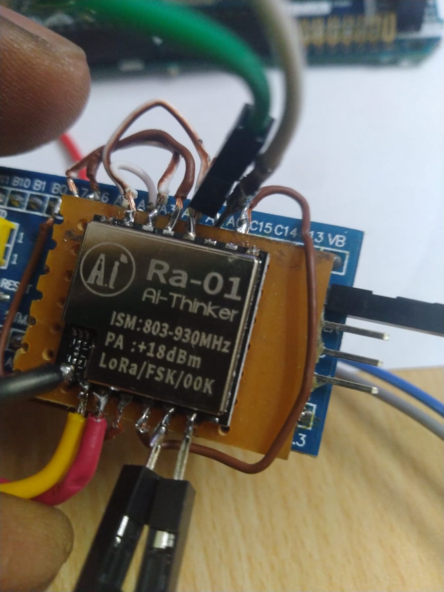
my lora module is this one
Well its perhaps not a surprise that the Pro Mini 3.3V @ 16Mhz is unreliable, that clock speed is out of spec for a 3.3V device. And the Mega2560 is normally a 5V device so needs logic level conversion circuits to connect to a 3.3V logic level lora device.
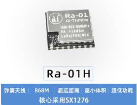
I was unaware that AI-Thinker actually makes a 800/900 MHz LoRa module.
The module is labeled as Ra-01 but that actually should be Ra-01H (the Ra-01 is 433/470 MHz only).

That is not true. Both ABP and OTAA will work (OTAA does not work if downlinks do not work),
but to get it working you will need to apply the workaround/patch that was already described in my above posts.
What caught my eye was that the module is labelled +18dBm, now +17dBm I would recognise.
Hi
TTN node that I built with Bluepill, rfm & platform.io: https://befinitiv.wordpress.com/2020/03/03/lorawan-node-with-bluepill-rfm95-platform-io/
In fact very similar to other projects posted here but so far I have not yet seen the bluepill,rfm,platformio combination floating around. Maybe it is of help to someone.
Best regards,
befi.
Hello JTP,
I have same problem it seems it consumes 0,37 mA at sleep mode. Did you solve your problem ?
You need to be specific about your hardware and software and make some serious attempts to track down the cause.
What low power mode is being used? List everything connected.
Holding a signal against an internal pullup will typically cost 100 uA, against an external one more. Leaving an I2C bus to a de-powered peripheral enabled will cost a lot. Leaving a TCXO running, similarly…
Hello cslorabox,
Brief summary :
Thanks for your quick response. As hardware, I am using STM32L412KB with Semtech1276 RFM9
5W module.They are communicating over SPI interface. I also have LIS3DH accelerometer which is connected to STM32L412 over I2C line. As a software I am using Konstantin Belyalov’s lora library for STM32 and LIS3DH library of Fabio Tota.
For STM32 i am using HAL driver. MCU is woken up every 30 seconds with RTC. I use standby mode for the rest of the time (I also tested it with stop mode as well). Lora is used in sleep mode. When i use lora without sleep mode 2,5 mA is consumed but when i make lora enter in sleep mode, consumption is decreased to 0,37 mA.
I tested different GPIO configuration in order to decrease consumption accoding to AN4899 but i could not make current consumption lower than 0,37 mA. At last, i changed all gpio pings to analog and pulldown.
“Leaving an I2C bus to a de-powered peripheral enabled will cost a lot”. What do you mean with this sentence ? Because in our desing I2C pins are pulled-up. I tested it with digital output pull-up but current consumption didn’t change. I didnt do something with TCXO, i only set lora into sleep mode. I think it should do itself.
Thanks in advance.