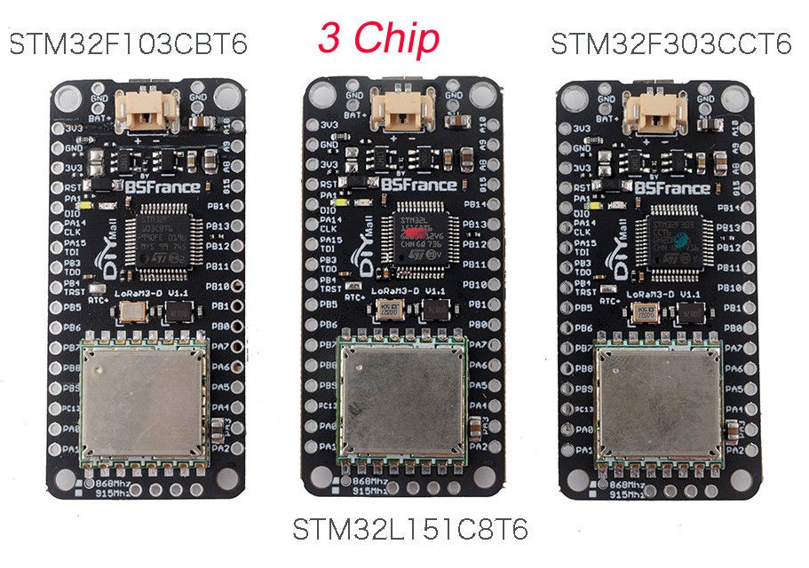
Update:
Above BSFrance LoRaM3-D STM32 boards are no longer available and BSFrance seems to be no longer in business. The BSFrance LoRa32u4 II boards (ATmega32u4 based, not STM32) are still available via DIYMall.

Update:
Above BSFrance LoRaM3-D STM32 boards are no longer available and BSFrance seems to be no longer in business. The BSFrance LoRa32u4 II boards (ATmega32u4 based, not STM32) are still available via DIYMall.
Those BSFrance / DIYMall LoRaM3-D boards look nice and promising!
STM32F103CBT6 Mainstream Performance line, ARM Cortex-M3 MCU webpage
LoRaM3-D F103 board datasheet
STM32L151C8T6 Ultra-low-power ARM Cortex-M3 MCU webpage
Interesting power specs for battery powered low power operation.
LoRaM3-D L151 board datasheet
STM32F303CCT6 Mainstream Mixed signals MCUs ARM Cortex-M4 core with DSP and FPU webpage
LoRaM3-D F303 board datasheet
All three boards are supported for Arduino IDE and support uploading of sketch via USB (DFU).

BSFrance: https://bsfrance.fr/58-lora-long-range?page=2
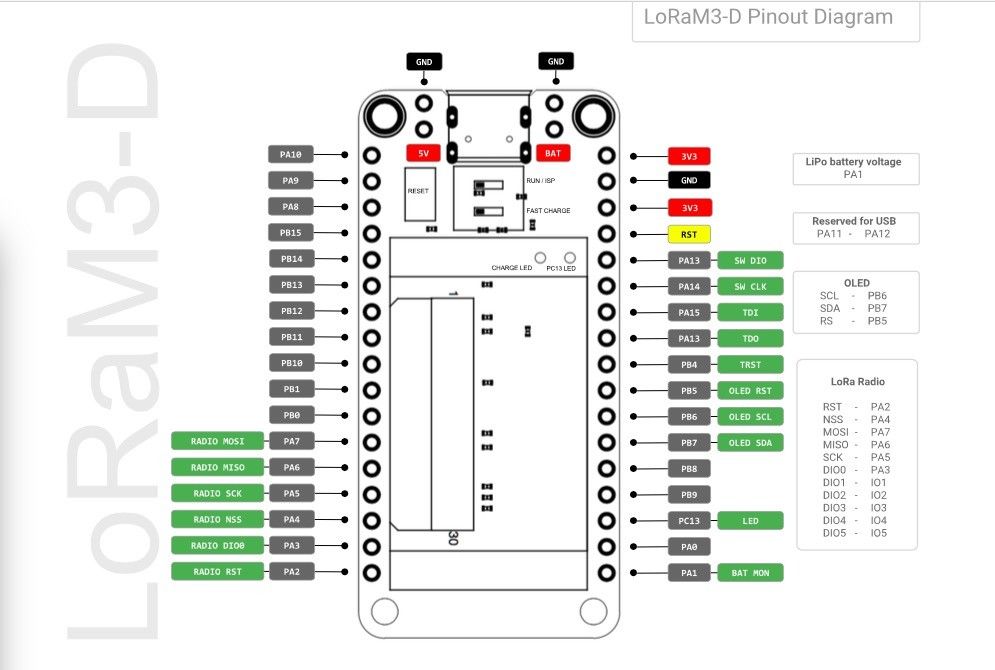
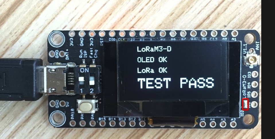
Note: Only DIO0 is wired. DIO1 to DIO5 are available as separate pads/pin holes on the narrow side of the board (to be manually wired when needed).
I fiddled with the STM32F303CCT6 version. But can’t get it to work with loramac-node stack, after extensive debugging I can’t get the rtc alarm A to fire the interrup service routine (isr).
Lmic is for arduino, which also does not work cause there is no SPI implementation for the f3.
And MiniMouse need mbed and an SPI driver c++ class as well.
If anybody got ttn working on the f3, please let me know.
Bas
Unfortunately that will not directly provide a solution for a generic STM32F303 board and Arduino.
The Arduino is supported by ST only for a limited number of STM32 versions and boards.
Then there is also the stm32duino ‘Arduino_STM32 by rogerclarkmelbourne’ alternative but that is for STM32F103 only (and not based on the official STM32 HAL).
The good news is that the LoRaM3-D F303 boards do support the Arduino Stack / IDE (based on official STM32 HAL) but unfortunately that is not a solution for existing generic STM32F303 boards.
I have STM32F103C8T6 boards running with Arduino stack and LMIC-Arduino, but that is F103 not F303.
Would you like to share that code for the “BluePill” ?
/Bingo
The pinout diagram shows that DIO1 to DIO5 should be available on IO1 to IO5.
I only see pins for DIO0 (DIO), DIO1 (IO1), DIO3 (IO3), DIO4 (IO4) and DIO5 (IO5).
IO2 appears missing. Where is DIO2 (IO2) available?
I love this one for 2 reasons
But would be great to have more documentation and schematic (to know the voltage divider ratio and the 2 charging mode ma)
Take care it’s a STM32 so would be great also to have doc on how to program it (environnement, source code, …)
I’m in France how can I order from France to France ?
Ah ah found more detail on another post
How you can order from France to France or from BSFrance to France? 
Just check 2 posts below the one you mentioned, here: The BARGAIN basement part 3
See BSFrance link on the bottom.
You can program it like an Arduino (with minor differences, e.g. port names instead of port numbers (like PB1, PA3, PC13 etc.). The Arduino IDE is supported (PlatformIO currently not (yet) supported).
They have written a proper Arduino Core based on official STM32 HAL which fully implements the F1, L1 and F3 series. A 4k boot loader which supports sketch uploading via USB (DFU) is included on all three boards.
I currently have a STM32 (STM32F103C8T6 ‘bluepill’) board with separate RFM95W module and OLED display running with the LMIC-Arduino and U8g2 libraries (a configuration similar to LoRaM3-D F103).

DIO2 is on a rectangulr pad just over DIO1
These pinholes re not connected, if he need to use them, he need to connect them
Only DIO0 is permanently connected to a STM32 GPIO
Hello.
For the STM32 F103 Version and the Arduino-IDE
Have a look :
http://www.stm32duino.com/viewforum.php?f=28&sid=70dbf1eab42b29cb98f366e162f7c4b3
I like the Solution from @tomtor : https://www.thethingsnetwork.org/labs/story/a-cheap-stm32-arduino-node
His Git : https://github.com/tomtor/Arduino_STM32
Öhm… We have a Link to Git from BSFRancesolutions?
Here it is : https://github.com/BSFrance/BSFrance-stm32
Greets
Cool! Any more information about your configuration? Blog or Git?
And what is U8g2 ???
Greets
That’s Oli Kraus display library
@bingo600 @Nordrunner
I will share it on github somewhere next week (or so), will take some time.
I will make available several ready-to-go Arduino sketches for a basic TTN node based on SX1276/RFM95W module and (optional) OLED I2C display, using Arduino-LMIC and U8g2 libraries.
A separate sketch per MCU/board. Each sketch can be used for both OTAA and ABP activation (configurable at compile time).
This will allow (new) users to get a new TTN node up and running quickly, without first having to deep dive in board specifics, find out which pins to wire to what, and without having to configure ports in the software first. Focus is on quickly getting the basics to work (sketch will only send a basic upstream message). You will only have to select the appropriate sketch for your board/MCU, (de)select any options and enter the required TTN keys/IDs. And when using separate components: wire them as documented in the sketch.
Currently planned: Several AVR ATmega32(U4), ESP8266, ESP32 and STM32 (x-pill) based boards.
Great!!!
Are you knowing Hiveeyes ?
They are monitoring Bee`s. A great Project!
They are looking for new nodes for transmitting there data`s. The BP was another candidate.
It is german, but feel free to talk in english. It is bilingual.
Greets
Nice to see you posting STM32 based stuff. 
Note: Some BME280 modules already have I2C pull-up resistors included (so should be checked first).
Thank you so much 

Looking forward to try it , i already have some rfm95’s
I might have one of those 0.96" SPI oleds in the drawer
/Bingo
Will be I2C displays.
SPI may be possible but more complex as it will possibly compete with the LoRa module for the SPI bus, resulting in LoRaWAN timing issues (LMIC-Arduino is not interrupt-driven). So not worth the hassle (for the €2.50 for a 0.96" I2C OLED display).
Thanks. I didn’t know about them.
What a coincidence: last week I met someone who also wants to monitor his bee’s.
shit!
on my WB i have an 1.8" TFT SPI 128x160 V1.1 Display i want to use.