Building it
Gutting the TTN Gateway
At this stage, I assume you've lost your fear of propping things open. The white lid of my TTN Gateway came off rather voluntarily, giving sight to the green PCB with its LoRaWAN goodness and blue shiny lights.

If you haven't done so already, disconnect the gateway from power and unscrew the antenna. The next step may differ for you, because my case had previously melted away and taken a weird shape. I had to use a bit of force to break the PCB out of the case, taking extra care not to bend the PCB and not to do any harm to the pigtail antenna connector, which is needed to connect the external antenna to the gateway.

The image shows the working PCB in its new home.
Cable routing
You need two openings in your outdoor case, one for the antenna cable, and one for the power supply. The cable glands are pretty self-explanatory, but I hadn't even known that they exist until I was told... First, you punch out the M20 holes from your box (mine just needed some encouragement with a light hammer and a screw driver). You then tighten the cable glands to the box, using the locknuts on the inside of the box. Then you thread your antenna and power cables through the cable glands. I left the tightening until I was satisfied with the final arrangement. Note if you're using the same components that I've proposed, the antenna cable connector on the antenna side fits through the cable gland, whereas the gateway facing antenna connector doesn't. Hence, first fit the antenna cable through the gland, then connect it up to the antenna. Make sure you're leaving enough antenna cable inside the box for the pigtail to connect it to the PCB, and sufficient power cable to allow yourself a bit of space when connecting and placing the AC/DC converter.
Power management
Note: I'm the last one who should give advise on dealing with potentially deadly electricity. I'm describing here what I did. This is not to encourage you to try anything stupid, in case you're not sure if you should or shouldn't...
Use a voltmeter to check the polarity of the 12V wall plug that came with the TTN Gateway. I decided to use the same barrel adapter for convenience, cutting it off the wall plug with about 10cm of cable remaining at the barrel. There are screw connectors on both the 12V and 220V ends of the power brick. First, connect the 220V terminals, then check for polarity on the 12V terminals, and make sure you can replicate the barrel's original polarity. I opted for a three-wire power cable because of the IP44 classification of the plug. The third wire is not needed, and I isolated it with electrical tape. While the power brick is rated 1A and less than the wall plug that came with the TTN Gateway, in practice this hasn't made a difference.
Connecting the antenna
Using the pigtail adapter that was previously needed for the stub antenna, the TTN Gateway PCB can connect to the BNC cable of the Aurel GP via the SMA-to-BNC adapter. I was a bit worried that the connection from antenna to BNC cable, from BNC cable to BNC/SMA adapter, from BNC/SMA adapter to the pigtail, and from the pigtail to the PCB would result in considerable signal loss. That may be. However, in the light of my performance improvements I'm absolutely happy with the current solution.
Closing and mounting
Before putting the TTN Gateway back into action, place the power brick and the PCB in the waterproof case. Make sure there are no free wires and that the connections cannot become lose. The PCB can be screwed to the case, however, I resorted to Blu-Tack to keep bits and pieces in place. I gave the gateway a test run before finally putting in the screws that seal the case.
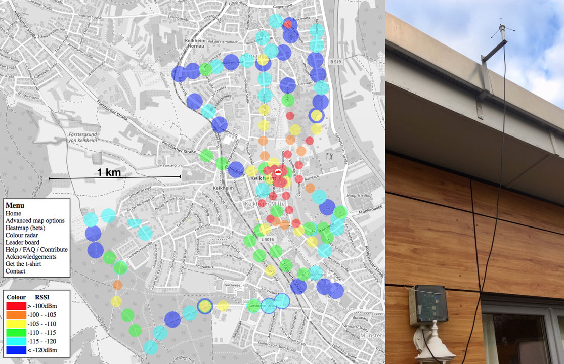
I attached the antenna to a piece of scrap metal, which I bent to fit our roof.


