Introduction
Get the parts
How to wire the Arduino Pro Mini, RFM95W and the Ublox Neo6M GPS
The software with LPP conversion
Upload and test
Build in the box
Conclusion
Introduction
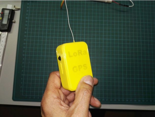
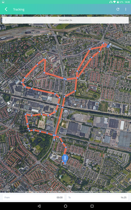
This LoRaWan GPS tracker uses the TTN Cayenne integration and shows your movements on a map in your Cayenne dashboard.
Built in a 3D printed enclosure, fastened with a rubberband on my front bicycle light, I did several bike tours around our city. This setup was 1 meter above the ground and the antenna was almost horizontal. I was amazed by the good results for about.... $20
The GPS tracker is built up with the following hardware components:
* Arduino Pro Mini
* RFM95 tranceiver
* Ublox NEO-6M GPS
* Lipo battery

* On/Off switch

* 3D printed enclosure
Get the parts
Here is an example where you can buy most of these components. Total cost about 16 euro. They are available through various online shops:
- Arduino Pro Mini
- RFM95W
- Ublox NEO-6M GPS
- On/Off Switch
- Lipo battery from an old Nokia phone or something like this
- Print or let print the 3D printed enclosure
How to wire the Arduino Pro Mini, RFM95W and the Ublox Neo6M GPS

- I did not use an external pcb for the connection between the Arduino Pro Mini and the RFM95W . These connections are made with several pieces of thin (.5mm) multistrand wire from an old usb cable.

- After finishing the wire connections, I covered the base of the antenna with a piece of heat shrink tube and glued it to the Arduino Pro Mini.

- The ceramic GPS antenna is soldered at the back of the GPS pcb.

- Hotglue used to fix the antenna coax
The Arduino > GPS connections:
- Arduino Pin 8 > TX Pin GPS
- Arduino Pin 9 > RX pin GPS
- Arduino VCC (rightside from A3 connection) > VCC GPS
- Arduino GND (between RST and RAW connection) > GND GPS
The Arduino > RFM95W connections:
- Arduino VCC > 3.3V RFM95W
- Arduino GND > GND RFM95W
- Arduino D4 > DIO0 RFM95W
- Arduino D5 > DIO1 RFM95W
- Arduino D6 > DIO5 RFM95W
- Arduino D7 > DIO2 RFM95W
- Arduino D10 > NSS RFM95W
- Arduino MOSI > MOSI RFM95W
- Arduino MISO > MISO RFM95W
- Arduino CLK > SCK RFM95W
The software with LPP conversion
This code is based onMathijs Kooijmans LMIC-Library and code parts from Bjoerns, Teumaat , and Frank
To make use of the TTN Cayenne Integration it is necessary to convert your code to the LPP format. More info in these Cayenne Low Power Payload docs
*************** Code with LPP conversion*******************
#include <lmic.h>
#include <hal/hal.h>
#include <SPI.h>
#include <TinyGPS++.h>
#include <AltSoftSerial.h>
#define LPP_GPS 136
static const int RXPin = 8, TXPin = 9;
static const uint32_t GPSBaud = 9600;
TinyGPSPlus gps;
AltSoftSerial ss(RXPin, TXPin); // RX, TX
static const PROGMEM u1_t NWKSKEY[16] = { Your Network Session Key};
static const u1_t PROGMEM APPSKEY[16] = { Your Application Session Key };
static const u4_t DEVADDR = 0xYour Device Address ; // <-- Change this address for every node!
const unsigned TX_INTERVAL = 20;
void os_getArtEui (u1_t* buf) { }
void os_getDevEui (u1_t* buf) { }
void os_getDevKey (u1_t* buf) { }
uint8_t coords[11];
static osjob_t sendjob;
static osjob_t initjob;
uint8_t cursor = 0;
uint8_t channel;
// Pin mapping
const lmic_pinmap lmic_pins = {
.nss = 10,
.rxtx = LMIC_UNUSED_PIN,
.rst = LMIC_UNUSED_PIN,
.dio = {4, 5, 7},
};
void get_coords () {
bool newData = false;
unsigned long chars;
unsigned short sentences, failed;
float flat,flon,faltitudeGPS,fhdopGPS;
unsigned long age;
// For one second we parse GPS data and report some key values
for (unsigned long start = millis(); millis() - start < 1000;) {
while (ss.available()) {
char c = ss.read();
Serial.write(c); // uncomment this line if you want to see the GPS data flowing
if (gps.encode(c)) { // Did a new valid sentence come in?
newData = true;
}
}
}
if ( newData ) {
flat=gps.location.lat();
flon=gps.location.lng();
if (gps.altitude.isValid())
faltitudeGPS = gps.altitude.meters();
else
faltitudeGPS=0;
fhdopGPS = gps.hdop.value();
}
//gps.stats(&chars, &sentences, &failed);
int32_t lat = flat * 10000;
int32_t lon = flon * 10000;
int16_t altitudeGPS = faltitudeGPS * 100;
int8_t hdopGPS = fhdopGPS;
channel = 0x01;
coords[0] = channel;
coords[1] = LPP_GPS;
coords[2] = lat >> 16;
coords[3] = lat >> 8;
coords[4] = lat;
coords[5] = lon >> 16;
coords[6] = lon >> 8;
coords[7] = lon;
coords[8] = altitudeGPS;
coords[9] = altitudeGPS >> 8;
coords[10] = hdopGPS;
}
void do_send(osjob_t* j) {
// Check if there is not a current TX/RX job running
if (LMIC.opmode & OP_TXRXPEND) {
Serial.println(F("OP_TXRXPEND, not sending"));
} else {
// Prepare upstream data transmission at the next possible time.
get_coords();
LMIC_setTxData2(1, (uint8_t*) coords, sizeof(coords), 0);
Serial.println(F("Packet queued"));
}
}
// Next TX is scheduled after TX_COMPLETE event.
void onEvent (ev_t ev) {
Serial.print(os_getTime());
Serial.print(": ");
switch(ev) {
case EV_SCAN_TIMEOUT:
Serial.println(F("EV_SCAN_TIMEOUT"));
break;
case EV_BEACON_FOUND:
Serial.println(F("EV_BEACON_FOUND"));
break;
case EV_BEACON_MISSED:
Serial.println(F("EV_BEACON_MISSED"));
break;
case EV_BEACON_TRACKED:
Serial.println(F("EV_BEACON_TRACKED"));
break;
case EV_JOINING:
Serial.println(F("EV_JOINING"));
break;
case EV_JOINED:
Serial.println(F("EV_JOINED"));
// Disable link check validation (automatically enabled
// during join, but not supported by TTN at this time).
LMIC_setLinkCheckMode(0);
break;
case EV_RFU1:
Serial.println(F("EV_RFU1"));
break;
case EV_JOIN_FAILED:
Serial.println(F("EV_JOIN_FAILED"));
break;
case EV_REJOIN_FAILED:
Serial.println(F("EV_REJOIN_FAILED"));
break;
break;
case EV_TXCOMPLETE:
Serial.println(F("EV_TXCOMPLETE (includes waiting for RX windows)"));
if (LMIC.txrxFlags & TXRX_ACK)
Serial.println(F("Received ack"));
if (LMIC.dataLen) {
Serial.println(F("Received "));
Serial.println(LMIC.dataLen);
Serial.println(F(" bytes of payload"));
}
// Schedule next transmission
os_setTimedCallback(&sendjob, os_getTime()+sec2osticks(TX_INTERVAL), do_send);
break;
case EV_LOST_TSYNC:
Serial.println(F("EV_LOST_TSYNC"));
break;
case EV_RESET:
Serial.println(F("EV_RESET"));
break;
case EV_RXCOMPLETE:
// data received in ping slot
Serial.println(F("EV_RXCOMPLETE"));
break;
case EV_LINK_DEAD:
Serial.println(F("EV_LINK_DEAD"));
break;
case EV_LINK_ALIVE:
Serial.println(F("EV_LINK_ALIVE"));
break;
default:
Serial.println(F("Unknown event"));
break;
}
}
void setup()
{
Serial.begin(115200);
Serial.println(F("Starting"));
ss.begin(GPSBaud);
// LMIC init
os_init();
// Reset the MAC state. Session and pending data transfers will be discarded.
LMIC_reset();
// Set static session parameters. Instead of dynamically establishing a session
// by joining the network, precomputed session parameters are be provided.
#ifdef PROGMEM
// On AVR, these values are stored in flash and only copied to RAM
// once. Copy them to a temporary buffer here, LMIC_setSession will
// copy them into a buffer of its own again.
uint8_t appskey[sizeof(APPSKEY)];
uint8_t nwkskey[sizeof(NWKSKEY)];
memcpy_P(appskey, APPSKEY, sizeof(APPSKEY));
memcpy_P(nwkskey, NWKSKEY, sizeof(NWKSKEY));
LMIC_setSession (0x1, DEVADDR, nwkskey, appskey);
#else
// If not running an AVR with PROGMEM, just use the arrays directly
LMIC_setSession (0x1, DEVADDR, NWKSKEY, APPSKEY);
#endif
#if defined(CFG_eu868)
// Set up the channels used by the Things Network, which corresponds
// to the defaults of most gateways. Without this, only three base
// channels from the LoRaWAN specification are used, which certainly
// works, so it is good for debugging, but can overload those
// frequencies, so be sure to configure the full frequency range of
// your network here (unless your network autoconfigures them).
// Setting up channels should happen after LMIC_setSession, as that
// configures the minimal channel set.
// NA-US channels 0-71 are configured automatically
LMIC_setupChannel(0, 868100000, DR_RANGE_MAP(DR_SF12, DR_SF7), BAND_CENTI); // g-band
LMIC_setupChannel(1, 868300000, DR_RANGE_MAP(DR_SF12, DR_SF7B), BAND_CENTI); // g-band
LMIC_setupChannel(2, 868500000, DR_RANGE_MAP(DR_SF12, DR_SF7), BAND_CENTI); // g-band
// LMIC_setupChannel(3, 867100000, DR_RANGE_MAP(DR_SF12, DR_SF7), BAND_CENTI); // g-band
// LMIC_setupChannel(4, 867300000, DR_RANGE_MAP(DR_SF12, DR_SF7), BAND_CENTI); // g-band
// LMIC_setupChannel(5, 867500000, DR_RANGE_MAP(DR_SF12, DR_SF7), BAND_CENTI); // g-band
// LMIC_setupChannel(6, 867700000, DR_RANGE_MAP(DR_SF12, DR_SF7), BAND_CENTI); // g-band
// LMIC_setupChannel(7, 867900000, DR_RANGE_MAP(DR_SF12, DR_SF7), BAND_CENTI); // g-band
// LMIC_setupChannel(8, 868800000, DR_RANGE_MAP(DR_FSK, DR_FSK), BAND_MILLI); // g2-band
// TTN defines an additional channel at 869.525Mhz using SF9 for class B
// devices' ping slots. LMIC does not have an easy way to define set this
// frequency and support for class B is spotty and untested, so this
// frequency is not configured here.
#elif defined(CFG_us915)
// NA-US channels 0-71 are configured automatically
// but only one group of 8 should (a subband) should be active
// TTN recommends the second sub band, 1 in a zero based count.
// https://github.com/TheThingsNetwork/gateway-conf/blob/master/US-global_conf.json
LMIC_selectSubBand(1);
#endif
// Disable link check validation
LMIC_setLinkCheckMode(0);
// TTN uses SF9 for its RX2 window.
LMIC.dn2Dr = DR_SF9;
// Set data rate and transmit power for uplink (note: txpow seems to be ignored by the library)
LMIC_setDrTxpow(DR_SF7,14);
// Start job
do_send(&sendjob);
}
void loop() {
os_runloop_once();
}
Upload and test

- Make sure that it is possible to upload code with a FTDI , even if the Arduin Pro mini is built in a box, so it is a good idea to solder pin headers in advance.
- Upload the code, power up and check the serial monitor in the Arduino ID
- For this node I disabled the Frame Counter Check ( TTN Console > Your GPS Device > Settings)
- Check your TTN console if you see some incomming data.
- If you added your device correct in your Cayenne portal then the RSSI and SNR must be visible in the left pane.

- And the map in the right pane.

- There is also a nice Cayenne app for your Android device available
Build in the box
The last step is to put everything in a suiteable box.


- I made a small 3D printed enclosure which consists of a top, inner and bottom part.

- The design reference was an old Nokia lipo battery, the largest part that fits on the bottom.
- I also glued 8x3mm Neodymium magnets in each corner.

- The On/Off switched is glued, as well.

- On top of the battery is the inner part with Arduino Pro Mini (RFM9W at the other side) and the Neo 6m GPS module.
- You have to drill or melt a hole in one side of the bottom part for the wire antenna
Conclusion
I have built several nodes and gateways in recent years. Nodes that measure temperature and humidity, nodes that work together with ttnmapper and nodes that sent alerts to my smartphone when motion is detected.
They are used for learning objects, demos and shown to everyone who is interested. In addition it is also very grateful to build a completely handy working device from scratch with all these various pieces hardware and available information.

This GPS tracker was another nice project and fastened with a rubber band on my bike or just lying on my car dashboard it works fine and yes, I know:
- I 'm using "activation by personalisation" instead of "over the air activation"
- Disabled my Frame Counters Checks
- Sending to much bytes in given time and ignore the fair acces policy
- There is no battery management. I have to open the box if I want to charge the battery or upload new code.
Anyway, lots of things to improve but it was a cheap nice project.
All the information used in these projects has been found on fora and documentation @ thethingsnetwork and MyDevices and the various githubs.
I hereby thank everyone who contributed to this. The only thing I did is combine, cut&paste and glue it all together ;-)


