Virtual and real sensors on 1CH-gateway (ESP)?

I installed https://github.com/things4u/ESP-1ch-Gateway-v5.0 and this mono channel gateway is working properly.
I want to add a sensor (ds18b20 or gps or … no matter for the moment I want to discover, learn and test ! ) on this deck but do not understand how to do it despite my long readings and research.

Some problems for the moment (yes I’m a newbie :wink:

First problem : I see a startup error

1:1:3. WiFi connect SSID=xxxx, pass=xxxxxxxxx
A WlanStatus:: CONNECTED to xxxx
LoRaSensors:: 
G ERROR:: addLog:: file=/log-0 does not exist .. rec=1

(idem after formatting again)

Second -but minor- problem : GATEWAYNODE = 1
#define GATEWAYNODE 1 in ESP-sc-gway.h but I have to pass "Gateway Node" to "ON" using the web server.

Third -and really big !- problem : I can not understand what I’m reading …
whether on the serial port monitor (IDE Arduino) or in the TTN console.
In other words, what can I do with the data displayed in https://console.thethingsnetwork.org/gateways/eui-xxxxxxxxxx/traffic ?

Indeed, for the moment so I do not know how to add sensors.
I simply note the display of a virtual node … that I have to demystify
So,if you could offer me links (tutorial) I would really appreciate them.
(and at the same time a link to learn how to insert a real sensor on this gateway (for example to read the tension or the temperature of the room in which I try to think or anything else ! )

Thank you in advance :grinning:
Tix

Looking at the source, you have to define your own code for reading sensors and putting their values in payload in the _sensor.ino file by modifying the LoRaSensors() function (which is only a sample). However, I did not try yet.

Regarding the first problem, it is not clear to me but at first installation likely the log file does not exist and will be created, but if you keep formatting, it will never exist. What happens at the second run without formatting?

Third: look at the payload format and write a decoder function for it in the payoloads format tab of the console.

Thanks a lot for your return UdLoRa,

Looking at the source, you have to define your own code for reading sensors and putting their values in payload in the _sensor.ino file […]

I have something to occupy my evenings until next year !

The example code below adds a battery value in lCode (encoding protocol) but
// of-course you can add any byte string you wish

Now, with your help, I must admit that I could have found it … but I did not find it alone … where to look!

Regarding the first problem, it is not clear to me but at first installation likely the log file does not exist and will be created, but if you keep formatting, it will never exist.

First : #define _SPIFF_FORMAT 1 (in ESP-sc-gway.h) and compile , upload ESP-sc-gway.ino and run
Second : #define _SPIFF_FORMAT 0 (in ESP-sc-gway.h) compile again, upload ESP-sc-gway.ino and run ==>

rst:0x1 (POWERON_RESET),boot:0x17 (SPI_FAST_FLASH_BOOT)
configsip: 0, SPIWP:0xee
clk_drv:0x00,q_drv:0x00,d_drv:0x00,cs0_drv:0x00,hd_drv:0x00,wp_drv:0x00
mode:DIO, clock div:1
load:0x3fff0018,len:4
load:0x3fff001c,len:808
load:0x40078000,len:6084
load:0x40080000,len:6696
entry 0x400802e4
ESP32 defined, freq=868100000 EU868
ARDUINO_ARCH_ESP32 defined
SPIFFS init success
Assert=Do Asserts
debug=1
readConfig:: Starting
M ERR:: readConfig, file=/gwayConfig.txt does not exist … Formatting

No doubt a big mistake on my part … and again ?

added December 30, 2018:
I just added in the file ESP-sc-gway.ino the following line:
#include <esp_spiffs.h
and that seems to have solved that problem …

Finally with regard to the third point.
I now know what I have to do: work and work again :wink:
I have read a lot of criticism on a gateway “1ch”: personally it already allows many discoveries around the configuration “lorawan” even before having transmitted any telemetry.
What do you hope for a few euros?

I think that, regarding the educational aspect, there aren’t many criticisms. Criticisms are mostly about building a network infrastructure where sub-standard components could become dominant, limiting some of the network capabilities (OTAA, ADR, etc).

The discussion about “criticism of a single channel gateway” should focus on the regulatory requirements to operate in the radio band in the country of operation. For example in Australia to work in the 915 band its a legal requirement to change channels with each transmission. The primary requirement is to reduce interference to other users of the same shared radio resource. Being an ISM band its used for all sorts of application, many of these are nothing to do with Lora. I remember thinking when reading the radio spectrum rules for AU915 that an 8 channel gateway may not comply, I had the feeling the regulators expected the radio transmitter to randomly change throughout all 64 channels allocated in the band.

Ok, thanks for your returns, UdLoRa and TonySmith :slight_smile:
I was referring to what I read here: http://things4u.github.io/DeveloperGuide/ArchitectureGuide/architecture.html (but this article may be out of date, TTN software both ESP 1ch other hand have evolved without doubt ?)
below is the excerpt in question

Single Channel Gateways

Single Channel gateways are LoRa devices that receive and transmit only on one channel and at one speed. This means that they will only receive a fraction (mostly 10% or so) of all LoRa messages that are transmitted in their area. However, they might come in useful in areas with less dense traffic or for private networks where we want to provide a service for only a limited set of well-known devices.

Single channel gateways have no downlink functions, so it is not possible for applications to send messages (back) to a device. However, and more important, they cannot forward Join Accept messages as well. This means that single channel gateways can only be used with ABP addressing. Also, cost of a single channel gateway is very much lower than a full-blown LoRa Gateway.

At the moment the TTN staging environment will accept data coming from Single Channel Gateways, and it will schedule downlink travel over these Gateways as well (which will never arrive at its destination). This means that a 1-ch gateway will seriously disrupt OTAA functions in areas where bot fullgateways and 1-ch gateways are present.

In future releases of the TTN it is expected that they will still accept messages in staging environment (for testing) but recognizing that the device is a single channel gateway it will not send any downlink traffic to that gateway. Whether the production environment of TTN in the future will still handle 1-channel gateways remains to be seen; TTN likes to provide service to full gateways and likes to get rid of single channel gateways for obvious reasons. On the other hand, nothing keeps people from building their own LoRa-like environment with single channel gateways. As the 433MHz and 868MHz bands are free to use for everybody (provided you do not use more than 1% air time), the networks have to cope with other traffic on these frequencies in some way.

that being said I come back to my beginner problems!
Who would have tested on ESP-sc-gway the “sensor” part and could help me to move forward?
I read in “sensor.ino”

// Also, the message format used by this gateway is LoraCode, a message format
// developed by me for sensor values. Each value is uniquely coded with an
// id and a value, and the total message contains its length (less than 64 bytes)
// and a parity value in byte[0] bit 7.

No doubt simplistic to perform the decoding … but, personally if I know how to take care of flowers and vegetables (yes, I will use LoRa to take care of them!) I remain unable to understand how to decode " Loracode “/” lcode "messages.
Just a simple example would take me a step further!
Thanks
Tix
ps : for the moment in my Arduino Ide Terminal I read messages like this
LoRaSensors:: Battery
G addLog:: fileno=1, rec=33: 1 F 44 0 3C 71 AF FF FF 88 B4 18 {“rxpk”:[{“tmst”:1572472280,“chan”:0,“rfch”:0,“freq”:868.099975,“stat”:1,“modu”:“LORA”,“datr”:“SF7BW125”,“codr”:“4/5”,“lsnr”:12,“rssi”:-107,“size”:16,“data”:“QLYUASYAVwEBN0mrC4hJTQ==”}]}

This is the Base64-encoded full LoRaWAN packet, including your encrypted application payload. Using an online decoder you can see that this matches a hexadecimal representation of 0x40B6140126005701013749AB0B88494D, which is what you’ll see in the gateway’s Traffic page in TTN Console. In the online decoder you’ll also see that the encrypted application payload is 0x3749AB when displayed as hexadecimal.

To decrypt that application payload, you’ll need the secret AppSKey, which is either hardcoded (for ABP devices) or has been sent during the Join Accept (for OTAA; which incidentally is supported by some single-channel test gateways, as some do support downlinks, though then your node might still try to use a different frequency if the first OTAA Join Request does not succeed, like for LMiC).

As TTN knows those secrets, TTN Console will show the decrypted application payload in the Data page of your application. No thinking required there.

If you need help decoding the application payload, then give us some example fake sensor values and their matching decrypted application payload, and a link to the documentation of that LoraCode format (probably this). (I won’t be spending time to help you on that though; see below.)

Also, to make the test gateway mimic a sensor, I guess the following from the documentation needs to be enabled, using the proper values from a dummy device in TTN Console:

GATEWAYNODE 1;
#if GATEWAYNODE==1
#define _DEVADDR { 0x26, 0x01, 0x15, 0x3D }
#define _APPSKEY { 0x00, 0x00, 0x00, 0x00, 0x00, 0x00, 0x00, 0x00, 0x00, 0x00, 0x00, 0x00, 0x00, 0x00, 0x00, 0x00 }
#define _NWKSKEY { 0x00, 0x00, 0x00, 0x00, 0x00, 0x00, 0x00, 0x00, 0x00, 0x00, 0x00, 0x00, 0x00, 0x00, 0x00, 0x00 }
#define _SENSOR_INTERVAL 300
#endif

While the online decoder accepts 00000000000000000000000000000000 for the secrets, obviously you’ll need to change those to match some device in TTN Console, to see any data there. Note that the online decoder now shows DevAddr = 260114B6 (which is in the non-encrypted LoRaWAN headers), and rejects the all-zeroes when validating the MIC, using the all-zeroes NwkSKey, so I guess you already made some changes there?

Or, you might actually see someone else’s true LoRaWAN packet?

Or, don’t waste your time on that at all? If you just want the temperature or air pressure around the WiFi-enabled ESP hardware, then you simply don’t need LoRaWAN at all.

I’d say, forget the fake LoRaWAN sensors. Instead add a single-channel test node to your setup, and put it at least a few meters from your gateway to truly dive into LoRaWAN.

1 Like

+1, that is: if you do not have other nodes, you do not need LoRaWAN because you already have WiFi . If you have them, then avoid the nice but not truly common situation of a gateway acting as a sensor (it is useful but for example to check gateway conditions).

1 Like

Thanks for your return,
My experiments have to be considered as a Lorawan discovery and idem with the use of the TTN console;)
1 / Of course there will be (before spring 2019 I hope !) nodes that will talk to this gateway
2 / Buit, for the moment, I have not received my rfm95w … and I still want to advance in the understanding of decoding data : that is why I’m picking with “lorasensor” !

I do not agree and I find, instead, that you have spent time answering me !!!
Your answer is very detailed and, by digesting it quietly, will allow me to progress in understanding
I also thank you for the links (it’s sad but I was not able to find the one to “loracode” and if I have yet sought!).

Finally, I thank you both (yourself and UdLoRa) to insist on testing this gateway with a real node!
… so I will pause this gateway waiting to have assembled a first rfm95w.

… I am sure to have new questions to ask about this nice forum (if, of course, the answer is not already in the archives;)

1 Like

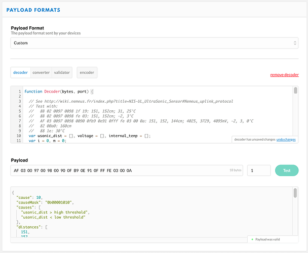
Just as an alternative: without any (fake) sensor you can define a payload function in a (dummy) application in TTN Console, and test that using the input field in TTN Console as well:

Click to see example decoder used above

This is discussed in Nemeus NIS-UL – Ultrasonic sensor Not the easiest example… See also Payload Formats [HowTo] - #3 by arjanvanb

function Decoder(bytes, port) {
  
  // See http://wiki.nemeus.fr/index.php?title=NIS-UL_UltraSonic_Sensor#Nemeus_uplink_protocol
  // Test with:
  //   8B 02 0097 0098 1f 19: 151, 152cm; 31, 25°C
  //   8B 02 0097 0098 fe 03: 151, 152cm; -2, 3°C
  //   AF 03 0097 0098 0090 0fb9 0e91 0fff fe 03 00 0a: 151, 152, 144cm; 4025, 3729, 4095mV, -2, 3, 0°C
  //   82 00a0: 160cm
  //   88 1e: 30°C
  var usonic_dist = [], voltage = [], internal_temp = [];
  var i = 0, m = 0;

  var mask = bytes[i++];

  // If bit 0 set: 1 byte indicating the number of measurements, else 1
  var nb_meas = mask & 1<<0 ? bytes[i++] : 1;

  // If bit 1 set: distances in centimeters, each 2 bytes unsigned MSB, 1 to 300cm
  if (mask & 1<<1) {
    for (m = 0; m < nb_meas; m++) {
      usonic_dist.push(bytes[i++]<<8 | bytes[i++]);
    }
  }

  // If bit 2 set: voltages in millivolts, each 2 bytes unsigned MSB
  if (mask & 1<<2) {
    for (m = 0; m < nb_meas; m++) {
      voltage.push((bytes[i++]<<8 | bytes[i++]) / 1000);
    }
  }

  // If bit 3 set: internal temperatures, each 1 byte signed integer [-128..+127]
  if (mask & 1<<3) {
    for (m = 0; m < nb_meas; m++) {
      // Sign-extend to 32 bits to support negative values, by shifting 24 bits
      // (too far) to the left, followed by a sign-propagating right shift:
      internal_temp.push(bytes[i++]<<24>>24);
    }
  }

  // Bit 4: reserved

  // If bit 5 set: cause for the measurement, else "periodic measurement"
  var cause = mask & 1<<5 ? bytes[i++] : 1;

  // We should have consumed all bytes, if not then just return the payload as hex
  if (i !== bytes.length) {
    return {
      'error': 'failed to parse payload',
      'payload': bytes.map(function(b) {
         return ('0' + b.toString(16).toUpperCase()).substr(-2);
       }).join(' ')
    }
  }
    // Format the results
  var result = {};
  // Show all 8 bits, ensuring leading zeroes
  result.mask = '0b' + ('00000000' + mask.toString(2)).substr(-8);

  result.numberOfMeasurements = nb_meas;
  result.distances = usonic_dist;
  result.voltages = voltage;
  result.temperatures = internal_temp;

  // Same data, grouped by measurement
  result.measurements = [];
  for (m = 0; m < nb_meas; m++) {
    result.measurements.push({
      distance: usonic_dist[m],
      voltage: voltage[m],
      temperature: internal_temp[m]
    });
  }

  result.cause = cause;
  result.causeMask = '0b' + ('00000000' + cause.toString(2)).substr(-8);
  result.causes = [];
  if (cause & 1<<0) {
    result.causes.push('periodic');
  }
  if (cause & 1<<1) {
    result.causes.push('usonic_dist > high threshold');
  }
  if (cause & 1<<2) {
    result.causes.push('usonic_dist < high threshold - high hysteresis');
  }
  if (cause & 1<<3) {
    result.causes.push('usonic_dist < low threshold');
  }
  if (cause & 1<<4) {
    result.causes.push('usonic_dist > low threshold + low hysteresis');
  }
  if (cause & 1<<5) {
    result.causes.push('forced manually');
  }

  return result;
}

Really interesting for me,
Thanks again arjanvanb.
Tix