Hi all ,
I am searching for a very slim (PCB) design of an Arduino (or comparable) besides an lora transceiver e.g. RFM95W. I like Charles mini-lora a lot and used them often. But now I need a design where they are maybe side-by-side to reduce height. The wisen whisper node is not bad because they didnt use pins to solder the break out board on the pcb but they have also the transceiver on one side and the arduino on the other side. The width of the PCB is not a problem, but the height.
It should run under a wooden floor.
Thanks for our ideas !
Br and happy easter
Peter
Is this too thick?
Definitive an option. I will try asap.
Thanks onehorse.
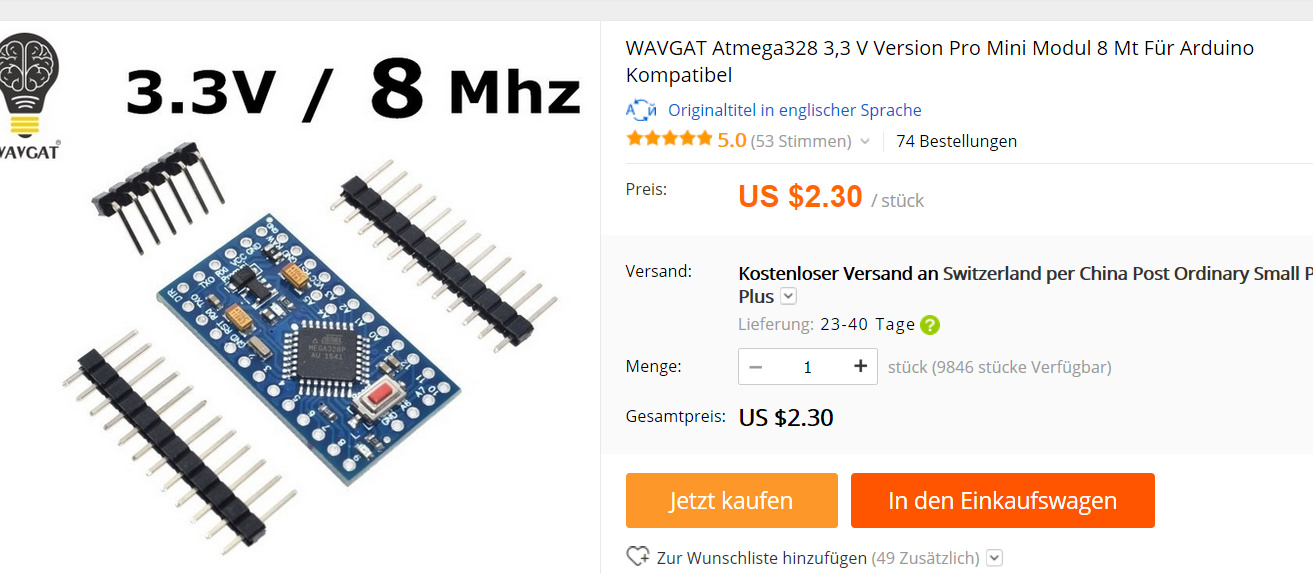
or a pro mini, its without a usb and cheap…

Hi Hanspeter,
thats the chip I also use. But with the PIN strip (which is also 3-4 mm) its too thick. I will try to mount the break out board direct on the pcb. Thanks for your ideas!
Peter
Breakout for what? RFM95W and sensors can be directly connected using thin wrap wires, pin strips are not really needed. But what kind of thin antennas and batteries are you thinking of for your flat design? For the antenna a piece of wire might be good enough and for batterie 3.6V round cells?
Breakout for the Arduino. The RFM95W fits ddirect on the “mini lora” PCB from Charles, two BME 280 I will wire with thin cable. Thats not the problem. Antenna will be only a piece of wire. Batterie I am thinking on a Lithium knob cell (CRxxx). Searching the most thin one. AA or AAA is to thick because it needs to be installed under the wooden floor.
The task is to send an temperature / humidity value pair once a day.
Its easy to mount a Pro Mini on a board without the pin strip.
Put a bit of kapton tape over the bottom of the Pro Mini and poke short bits of solid wire through the holes and solder in place.
Thats a brilliant idea ! I will try.
Br Peter
And where the kapton covers the holes in the Pro Mini, poke small holes in the Kapton with a needle, makes adding thew short wires easier.
Do the corner holes first. You can hold the Pro Mini accuratly in place by poking some cocktail sticks thru some of the free holes.
Sounds like you have experience in such work 
I will do exactly in that way.
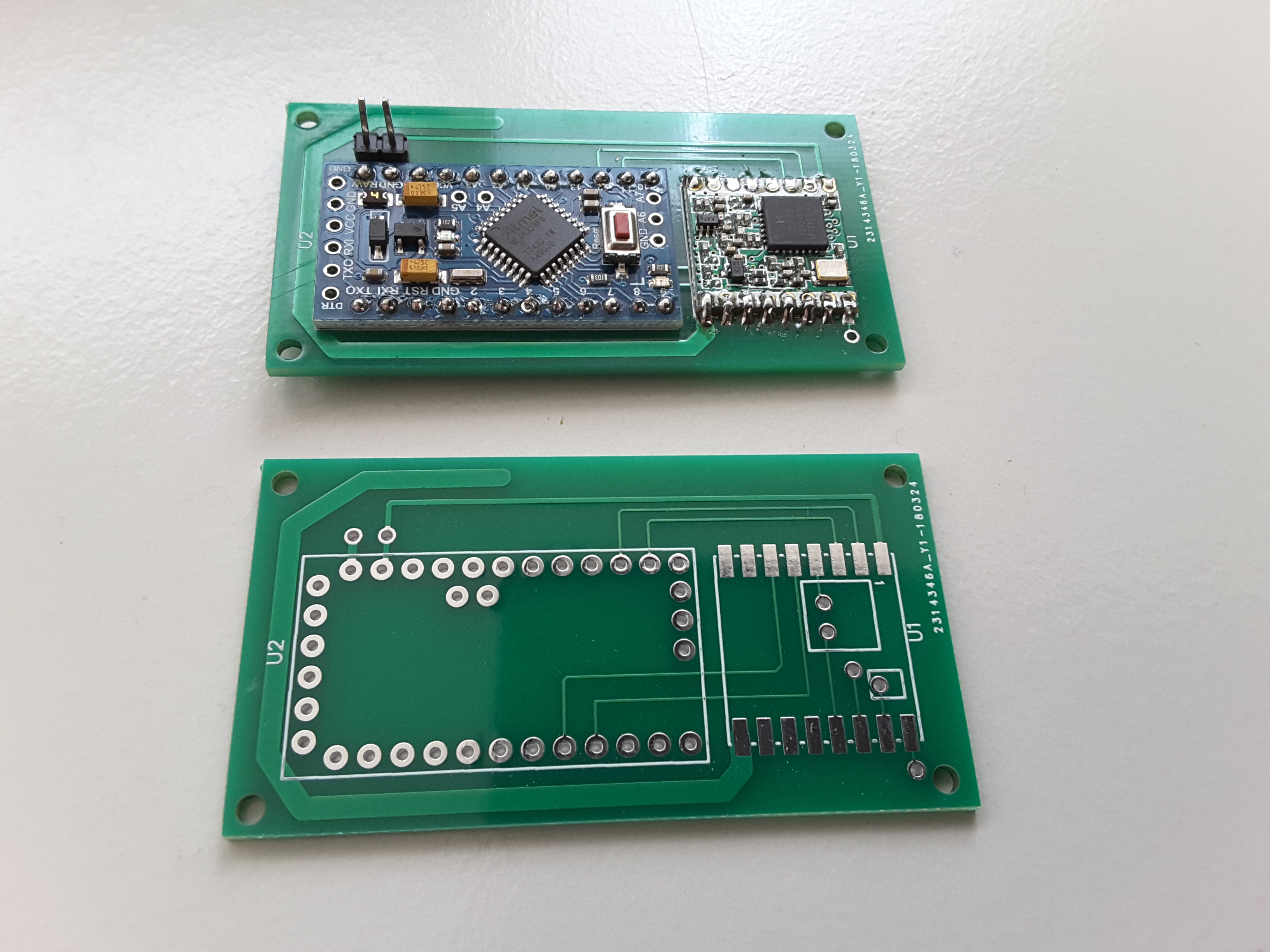
First I thought about a new pcb layout where the arduino and the RFM95W are side by side on the pcb. But the mini lora design is nice and its worth a try of course. So I can keep the existing pcbs.
Thanks a lot !
Br Peter
Or solder the pin strip to one of the boards, remove the plastic, put the other board on, solder and snip of the excess material. That way you do not have to cut-and-strip a lot of wires.
Yes, but do use the kapton or some other spacer, if the pads on the PCB or the Pro Mini do not match in size you can get shorts … as I once discovered.
Yes, thats exactly what I was afraid of. And I think the best way to avoid that is to put some isolating foil (like kapton tape) in beetween the brake-out board and the pcb.
…or forget the breakout board, mount everything on a thin isolation foil and wire everything side by side which would make it really flat…
I am thinking about mass production and for that a pcb for mounting the components would be helpful. Ideally with a side-by-side design of the arduino and the RFM95. So when I need to solder 5000 sensors on such a thin isolation foil I would need ages I assume 
But I appreciate all ideas HanspeterH.
Wouldn’t it make more sense to use a separate at328 instead of an entire arduino if you’re talking about those quantities? Besides, if you consider the size of the smd version likely even placing it next to the rfm would make sense.
True. You are totally right. For that I would need a custom pcb. And I would need to bring this board to a reasonable low value for the deep sleep power consumption, because its mounted under the floor so (besides harvesting or inductive charging ideas) no chance to exchange the battery if you use a knob cell.
Of course the new information to be able to produce 5000 boards makes the whole thing totally different…
I think the the way to go depends on
- the time you have until you must deliver the first 100 devices
- the possibility of a staged production and delivery (e.g. first 100 by hand, next 1000 manufactured)
- the money and time you have for this project to build a single board solution, i.e. for board design, test, error correction, production setup in china…
I think - it is unrealistic, to to build more than 100 boards by hand,
- even soldering 1000 wire antennas only is unrealistic, the boards need a pcb antenna
- how will you load the SW into so many devices, Is there a need for mass configuration or are all the same?
- the boards may need a megnetic actuated switch to restart them or a another contactless capability
- how will you identify the individual sensors if you do not get uploads any more
- can you exchange failing devices? How long must the battery last?
-etc. etc.
Maybe you can ask a professional and get some guidance/consultancy and be willing to pay for that,
What about this design? 