No sorry, these brackets came with the enclosure, but they are very basic L-shaped
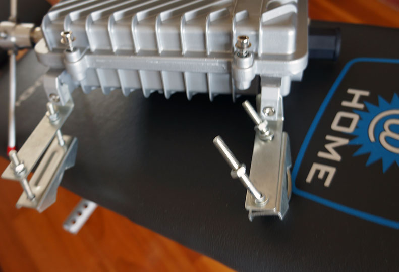
No sorry, these brackets came with the enclosure, but they are very basic L-shaped

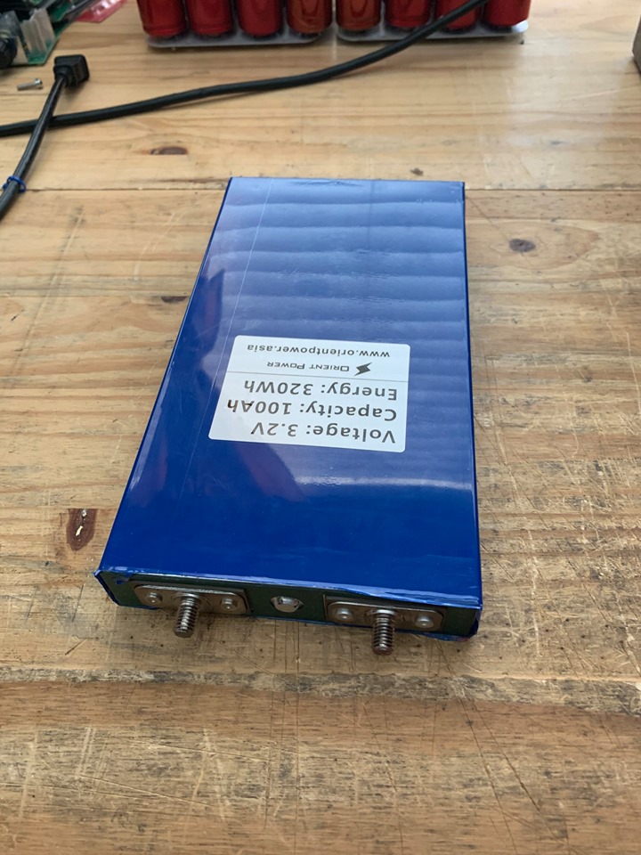
BIG Batteries!
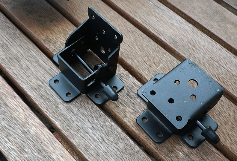
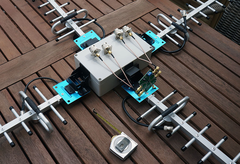
oops… almost made a big mistake, the yagi’s shouldn’t be mounted horizontal but vertical which
means I’ll have to rotate the hinges…which means it doesn’t fold like I wanted in ‘transport mode’ 
relax … first some inspiration 
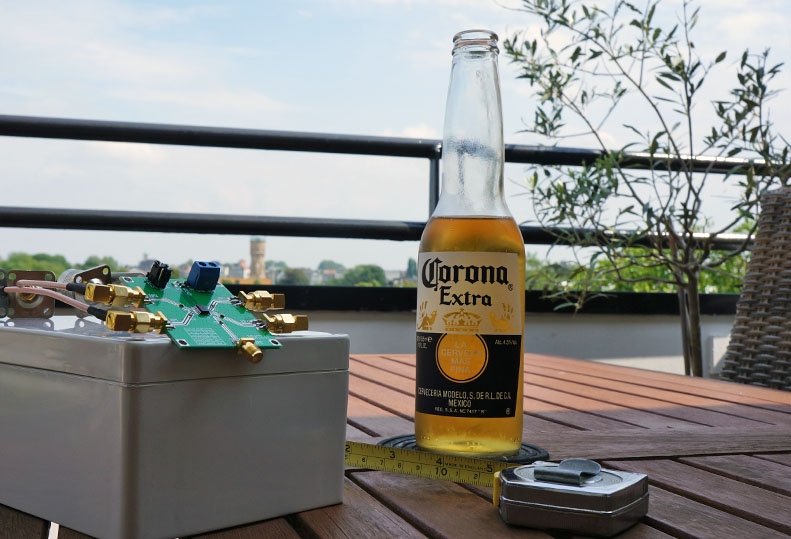
impression from this 3 day festival 
1 - https://www.youtube.com/watch?v=_ym0nJ506YQ
2 - https://www.youtube.com/watch?v=p24SNi7RKaU
3 -
Great news,
like @pe1mew I removed diode, LDO, put my my sketch with ULPNode lib and tadaaaaaaa 4.5µA
I can switch from SI7021 (Temp/hum) to TLS2561 (Light) reset the board and that is.
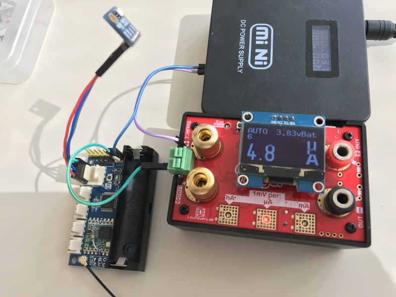
I also removed LDO from SI7021 board to gain between 5/10 µA
And at least, but not least, since I’m not going to works on more (just maintenance) I will open source ULPNode library and some demo sketch, including this one.
The library is very powerfull and can manage variety of sensors, LowPower and some feature such as removing power from sensors/RF modules if hardware is designed for. It could also manage TPL5110 and wake from switch interrupt
But the drawback is that even if the code is completely commented, with so much features and so much boards involved, rich technical skills are needed.
So I can’t release it without any documentation nor code.
So if someone want to test it, use it, investigate and write documentation (even a beautiful readme.md) I can create some private repo to my github and give you access before release to public.
Anyway, I would offer only to people that would invest time and that have proove their contribution to the community (here or elsewhere, hardware or software). It can be several people of course, no matter. More than that people using my boards would be appreciated because they would be able to test and provide once finished, code and board totally open sourced.and working.
During test and documentation, of course I will be available to help and answer question.
I know It may not the right place, but may be admin could create a topic for that, just let me know @BoRRoZ
that’s indeed great news Charles… tnx !, you know I had a peek in the source but looong time ago, of course I never used it outside of the 'lab.
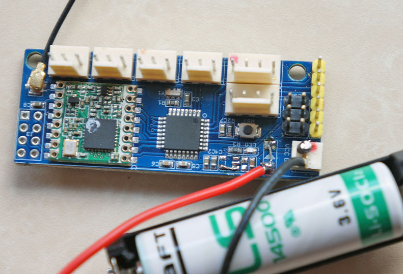
Just in time, I’ve finally burned the bootloader, made the @pe1mew hardware mod , bought an @Charles battery and was looking to integrate some code snips … this would be perfect .
I’m test volunteer Charles ! (only without BME280 at the moment- waiting)
well… nobody noticed , but I’m no longer ‘admin’, but still ‘involved’ So off course we can open a topic for that, you may do that yourself to Charles (I can do it too ’ CH2I ULPNode library open sourced !! ’ ?)
btw did you remove the LED also ?
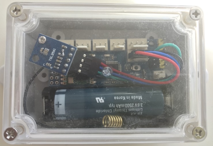
Not the best assembly, but this a cheap digital LoRaWAN Luxmeter connected to TTN, ready for years?

Nice, I let you doing it if you don’t care, may be change title to indicate for now just for contributors/testers
![]()
Thanks
Nope, the led can’t be using during transmit/receive, connected to SPI clock used by RFM95, that’s a same, because I have no indicator (join, transmit, receive, …) like on Mini LoRa
And the Cayenne LPP format magic
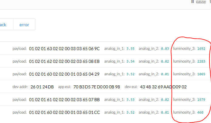
ok… I’ll write an introduction with some links to your work and BLOG
btw… Cayenne LPP also integrated ?
Well, yes sensors format but I don’t use the library, just hard code value depending on sensor
    uint8_t len = 0;
    uint8_t dev_idx = 1;
    uint8_t payload[32] ; // Max, not all will bu used, len is calculated on each data added
    uint8_t *p=&payload[0];
    uint16_t value;

    // This is very important, since we need to check battery voltage
    // you don't need to do this each wake up, but twice a day sounds good
    ulpn.readVcc();
    value = ulpn.readVBatAverage() / 10;
    *p++ = dev_idx++;
    *p++ = LPP_ANALOG_INPUT;
    *p++ = value >> 8;
    *p++ = value;

    #if DEBUG > 1
    DebugF("Vcc=");
    Debug(ulpn.Vcc());
    DebugF("mV VBat=");
    Debug(ulpn.VBatAverage());
    DebuglnF("mV");
    DebugFlush();
    #endif

    value = ++frameCounter;
    *p++ = dev_idx++;
    *p++ = LPP_ANALOG_INPUT;
    *p++ = value >> 8;
    *p++ = value;

    ulpn.i2cInit(true);

    #ifdef USE_SI7021
    if (ulpn.status() & RF_NODE_STATE_SI7021) {
      // Do a reading values OK ?
      if ( ulpn.si7021_readValues()==0 ) {

        // Now 291 means 29.1
        value = ulpn.SiTemp()/10 ;

        #if DEBUG > 0
        DebugF("Temp=");
        Debugln(value/10);
        #endif

        *p++ = dev_idx++;
        *p++ = LPP_TEMPERATURE;
        *p++ = value >> 8;
        *p++ = value;

        value = ulpn.SiHum();
        #if DEBUG > 0
        // Now the RH value
        DebugF("Hum=");
        Debugln(value);
        #endif
        *p++ = dev_idx++;
        *p++ = LPP_RELATIVE_HUMIDITY;
        *p++ = value*2;
      }
    } else {
      #if DEBUG > 0
      DebuglnF("No SI7021");
      #endif
    }
perfect !


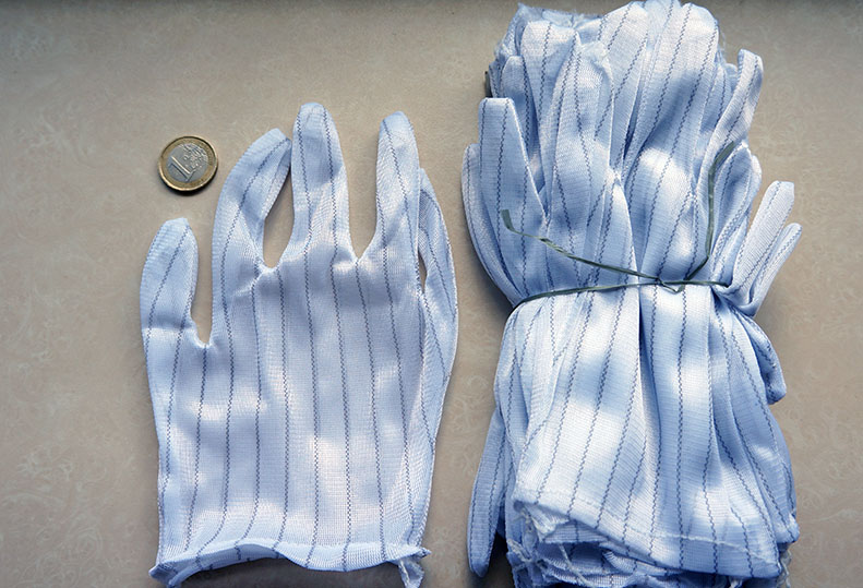
I thought 'anti static ect ’ and they looked ok on the pictures So I ordered them.
arrived today, I could fit 3 fingers  … must be for little chinese children in Iphone factory’s
and the quality… aaargh 
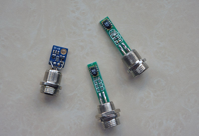
Simple, no regulator, nothing, just what you need
Nice isn’t it ?
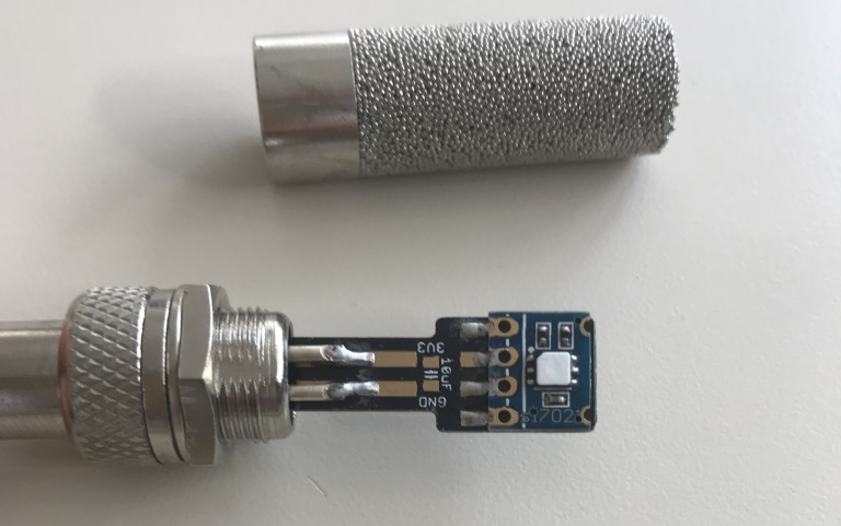
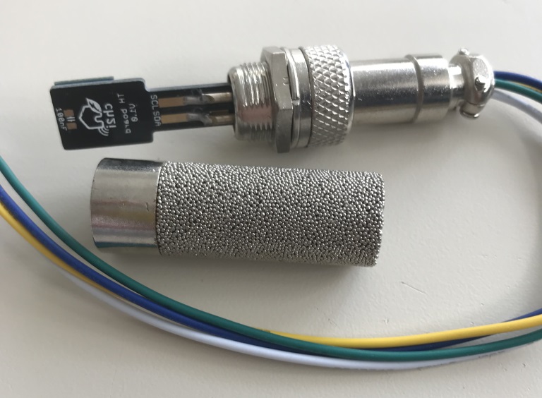
yep… looks very nice. 
I did that too, but noticed problems after a while with humidity values not being correct with a sensor
inside that enclosure.
Interesting, did you find out the issue? moisture on the sleeve?
yes inside … very fine, gave most problems in cold weather/after rain, when the droplets formed
related