Switch off devices attached to board to save energy

Hi all, thanks in advance. Sorry for my bad english.

Hi have a LilyGo TTO T-BEAM board, and i’m developing a project with low power requeriments. I have a GY-521 accelerometer withMPU-6050 and a pulsometer like https://pulsesensor.com/ that send’s their information to my LoraWAN gateway periodically.

Problem i have is that GY-521 and Pulsometer are switched on with their leds on even on deep sleep mode of ESP32, because both are connected to VCC 5V pin of the board and that pin always output power.
I understand that is a risk use digital GPIO PIN to power each device, but this devices uses very low current, around 10mA each one, perhaps board can support it. or not?

On the other hand i think is possible to make a switch with a mosfet, but i don’t know how do that, and don’t know if this solution is really good for save energy, or perhaps mosfet will consumpt same energy when devices connected to it are switched off.

many thanks!.

You can switch devices off by switching the VCC line with a MOSFET or there are high side switches designed for the purpose.

However, you will almost inevitably either have to switch all devices off, or isolate the pins that connect devices such as the I2C or SPI connections.

When a device is powered off all connected pins are effectivly shorted to ground, which can cause excess current to flow elsewhere.

If you have a T-Beam V10, you can use features of AXP192 power management chip to control various onboard voltages.

Many thanks, i saw this reed relay:
https://www.jameco.com/z/EDR2D1A0500Z-Excel-Cell-Electronics-Reed-Relays-SPST-NO-0-5A-5VDC-500Ohm-Thru-Hole_138431.html
But i’m not sure if using really i’m going to save energy…
I have this board,
http://www.lilygo.cn/prod_view.aspx?TypeId=50033&Id=1074
and it have AXP chip, I can’t find documentation of power management but this


It would work?
Thanks!!

The MPU6050 itself should only consume about 5 uA if you put it in sleep mode. What you are seeing is probably the rest of the circuitry on the GY521 - the regulator, and even the unnecessary power LED. If you already have a suitable supply in the node you can rework things to use that directly.

1 Like

Hi! I think that github contribution is yours, i’m seeing power.cpp, and is exactly i need. Can you tell me how can implement a simple script that only cut off VCC disabling LORA, GPS and devices connected to VCC PIN?
Many Thanks!!!

This is not correct. What will happen for the majority of devices is any input voltage present on a pin will effectively be connected to the VCC of the device through the input protection diode of the pin where the voltage is present. This is why devices will often continue to operate when power is removed from their respective VCC pins.

Put more simply, when a device is powered off, the I/O pins of the device are effectively connected to VCC of the device.

2 Likes

Yes, but depending on the drive impedance of the I/Os pulling it up, Vcc may end up at whatever fraction of a volt FETs just start to turn on and the part draw noticeable current.

So for example something sitting on an I2C bus may jam the bus, rather than operate off of it.

I said ‘effectivly’ not that the were actually connected to ground.

The diodes do indeed connect the I/O pins of the device that has been powered down to the VCC of that device, but since the VCC of that device is no longer connected the internals of the device will now pull the pin down towards ground.

The effect, as @cslorabox suggests is that the pins such as I2C and SPI will be pulled down towards ground and often cease to operate correctly, for active devices still connected to such pins.

As far as I understand with I2C the two I2C lines (SDA & SCL) are connected to open collector transistor/open drain mosfet inside the device. I have assumed powering down the Vcc line on the device will send these two lines into high impedance and the device does not draw current from these lines.

Anyone able to comment if my assumption is correct.

Thinking about a bit more, I have only considered the line driver side, there is circuitry in the device to monitor the I2C lines and this could easily draw current when Vcc is removed.

I may test some of my sensors in the next few days.

That is absolutely incorrect for most parts.

The reason is that there are protection diodes from the inputs to the supply rails on most parts. If the input is allowed to forward bias that diode by being higher than the supply rail by a sufficient fraction of a volt, current will flow and it will start to try to lift the supply rail. The pullups on an I2C bus may not be enough to power the part, and let the I2C bus work again even for talking to other parts, but putting just a few kilo ohms across most nodes battery packs would lead to a very premature battery death.

Some parts rated for I/O voltage above the supply may not have this input structure. Or they may have it, but be rated for a higher voltages with a series resistor and to tolerate a certain amount of injection current, which from a battery consumption point of view is still a major problem.

Your options are basically:

  • Keep parts powered, but put them in a low power sleep mode

  • Take the entire I2C bus low, probably by driving its pullups from a GPIO or from the supply of the peripherals turned off.

  • Segment the I2C bus. The common pass-MOSFET level translator circuit also works when the low voltage (but not the high voltage) side is shut down along with its pullup. It will also work if the voltage are the same on both sides, just don’t apply it backwards to a voltage difference.

  • Use an unique I2C bus per target, possibly bit banged, so that you can power it down. Or use some other interface.

  • Find parts with an input structure that allows the I/O voltage to be higher than the supply not only without exceeding ratings, but without causing milliamp current draw

1 Like

Thanks @cslorabox I need to review my power management circuits as I may be wasting energy.

I just realised I forgot to mention I do power down the I2C pull-up resistors as well.

While my existing sensors have a sleep mode I still switched the Vcc line as a precaution as I can’t guarantee future sensors will have the same capability. As a result I probably have my existing sensors in full sleep mode but could have problems in the future. Thanks again

In addition to @cslorabox’s comments, whenever I have built a circuit that requires some I2C parts to be left accessible (RTC or FRAM for instance) when other I2C parts are powered down (sensors, displays) I have used an I2C bus isolator, such as the TCA4311.

2 Likes

First make sure you have T-Beam V10, with earlier versions it’s not possible.
Power channels of AXP192 are used on T-Beam V10 as follows:

DCDC1 0.7-3.5V @ 1200mA max → OLED
DCDC2 → unused
DCDC3 0.7-3.5V @ 700mA max → ESP32 (keep this on!)
LDO1 30mA → GPS backup battery
LDO2 200mA → LORA
LDO3 200mA → GPS

You can cut off all above channels by software. Use the AXP202x library.
If you cut off DCDC3 you cut off the ESP32. This should be kept on during sleep.
If you cut off LDO1 GPS chip will loose it’s current almanach data, thus will need a cold start after restart. So this should be kept on, when GPS is used. If you don’t need GPS, you man cut LDO3 and take out the small backup battery.

If the LoRa device is the only SPI device you want to power down, you can get the sleep current for that down to 0.2uA (typical) by appropriate register writes.

Hi, as said here, https://github.com/lyusupov/SoftRF/wiki/Prime-Edition-MkII
I have T22_V1.0 20190612 board which is T-BEAM V10.
IMG_20191004_162200
Then i try to connect VCC pin of both devices (Gyro and Pulsometer) to DCDC1, then perhaps could power down that pin

Yes, that should work. DCDC1 can drive up to 1200mA.
Don’t forget to program approriate voltage for DCDC1, depending on the devices you want to attach. Look at my power.cpp as example.

DCDC1 is wired to header 3V3 pins.

Thanks, 2 questions?
DCD1 can ouput 5Volts?
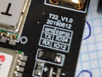
What is the AXP Primary Address of my board? 0x34 ??
ketch always say that initialization failed
I have this simple sketch, i think that at any moment i switch off (I hope no damage it) lora and i can’t switch on again (it outputs error):

17:21:06.903 -> FAILURE
17:21:06.903 -> /home/carlos/Arduino/libraries/arduino-lmic-master/src/lmic/radio.c:818

// Basic config
#include “axp20x.h”
#define AXP192_PRIMARY_ADDRESS (0x34)

AXP20X_Class pmu;

void AXP192_power(bool on) {
if (on) {
pmu.setPowerOutPut(AXP192_LDO2, AXP202_ON); // Lora on T-Beam V1.0
pmu.setPowerOutPut(AXP192_LDO3, AXP202_ON); // Gps on T-Beam V1.0
pmu.setPowerOutPut(AXP192_DCDC1, AXP202_ON); // OLED on T-Beam v1.0
// pmu.setChgLEDMode(AXP20X_LED_LOW_LEVEL);
pmu.setChgLEDMode(AXP20X_LED_BLINK_1HZ);
} else {
pmu.setChgLEDMode(AXP20X_LED_OFF);
pmu.setPowerOutPut(AXP192_DCDC1, AXP202_OFF);
pmu.setPowerOutPut(AXP192_LDO3, AXP202_OFF);
pmu.setPowerOutPut(AXP192_LDO2, AXP202_OFF);
}
}

void AXP192_init() {

if (pmu.begin(Wire, AXP192_PRIMARY_ADDRESS)) {
  Serial.println("AXP192 PMU initialization failed");
}
else {

Serial.println(“Initialization…”);
// configure AXP192
pmu.setDCDC1Voltage(3300); // for external OLED display
pmu.setTimeOutShutdown(false); // no automatic shutdown
pmu.setTSmode(AXP_TS_PIN_MODE_DISABLE); // TS pin mode off to save power

  // switch ADCs on
  pmu.adc1Enable(AXP202_BATT_VOL_ADC1, true);
  pmu.adc1Enable(AXP202_BATT_CUR_ADC1, true);
  pmu.adc1Enable(AXP202_VBUS_VOL_ADC1, true);
  pmu.adc1Enable(AXP202_VBUS_CUR_ADC1, true);

  // switch power rails on
  AXP192_power(true);

  // I2C access of AXP202X library currently is not mutexable
  // so we better should disable AXP interrupts... ?

#ifdef PMU_INT
pinMode(PMU_INT, INPUT_PULLUP);
attachInterrupt(digitalPinToInterrupt(PMU_INT), PMUIRQ, FALLING);
pmu.enableIRQ(AXP202_VBUS_REMOVED_IRQ | AXP202_VBUS_CONNECT_IRQ |
AXP202_BATT_REMOVED_IRQ | AXP202_BATT_CONNECT_IRQ |
AXP202_CHARGING_FINISHED_IRQ,
1);
pmu.clearIRQ();
#endif // PMU_INT

  Serial.println("AXP192 PMU initialized");
}

}

void setup() {
Serial.begin(115200);
// put your setup code here, to run once:
AXP192_init();
AXP192_power(true);
}

void loop() {

}

and if you completely power down, some I2C devices need to be re-initialised (takes time too)
first thing to do after waking up … like coffee in the morning :wink:

3 Likes

DCDC1 can be set 0.7 … 3.5V.
If you need 5V on T-Beam you must use VBUS, and cannot switch off.

0x34 is I2C address of AXP192.
Be careful to set appropriate voltage by
pmu.setDCDC1Voltage(3300)
and AFTER enable the channel by
pmu.setPowerOutPut()

If you can’t initialize the AXP192 chip you perhaps ran into i2c bus problem. Increase log level and watch out for i2c bus errors.