Hello everyone,
I hope you can help me in getting the LoRaMAC-node library to work with my hardware.
I am using a Nucleo-L476RG Board + Dragino 1.4 with a SX1276 module. What I already did is:
- download the latest codebase of LoRaMAC-node from github.
- copy
src/boards/NucleoL476/sx1276mb1mas-board.ctosrc/boards/NucleoL476/dragino14-board.cand add the target in the matching CMakeLists.txt. - Change the pins in
src/boards/NucleoL476/board-config.haccordingly. - Turn on OTAA and fill in the Credentials in
src/apps/LoRaMac/classA/NucleoL476/Commissioning.h. - Compile the example for ClassA in
src/apps/LoRaMac/classA/NucleoL476.
The build is done with this command:
build
cmake 	-DCMAKE_BUILD_TYPE=Debug \
		-DCMAKE_TOOLCHAIN_FILE="../cmake/toolchain-arm-none-eabi.cmake" \
		-DAPPLICATION="LoRaMac" \
		-DCLASS="classA" \
		-DCLASSB_ENABLED="OFF" \
		-DACTIVE_REGION="LORAMAC_REGION_EU868" \
		-DREGION_EU868="ON" \
		-DREGION_US915="OFF" \
		-DREGION_CN779="OFF" \
		-DREGION_EU433="OFF" \
		-DREGION_AU915="OFF" \
		-DREGION_AS923="OFF" \
		-DREGION_CN470="OFF" \
		-DREGION_KR920="OFF" \
		-DREGION_IN865="OFF" \
		-DREGION_RU864="OFF" \
		-DBOARD="NucleoL476" \
        -DRADIO="sx1276" \
        -DUSE_RADIO_DEBUG="" \
        -DMBED_RADIO_SHIELD="DRAGINO14" .. && make -j4
You can find my current codebase at https://github.com/Luddi1/LoRaMac-node.
After uploading I get following output on the UART:
Serial output
###### ===== ClassA demo application v1.0.RC1 ==== ######

DevEui      : 00-07-redacted out-F5-A7
AppEui      : 70-B3-redacted out-01-98-1D
AppKey      : 47 8C E2 76 redacted out B2 3A CC 3D


###### ===== MLME-Request - MLME_JOIN ==== ######
STATUS      : OK
###### ===== JOINING ==== ######

###### ===== MLME-Confirm ==== ######
STATUS      : Rx 2 timeout

###### ===== MLME-Request - MLME_JOIN ==== ######
STATUS      : Duty-cycle restricted

###### ===== MLME-Request - MLME_JOIN ==== ######
STATUS      : Duty-cycle restricted

###### ===== MLME-Request - MLME_JOIN ==== ######
STATUS      : Duty-cycle restricted

...
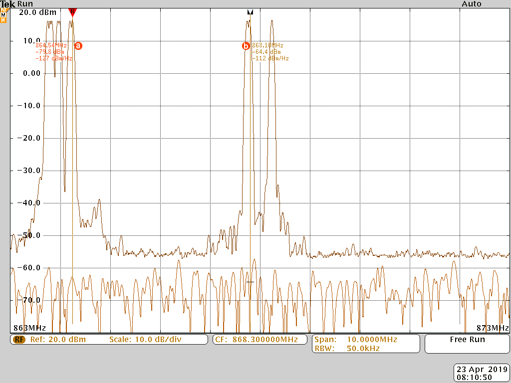
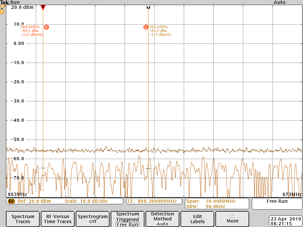
And the there seems to be no traffic at my local gateway. As I have no access to a spectrum analyzer at the moment I do not know if the module sends anything. But I can do that in the next days if it helps.
Also the gateway and this exact setup works because following this guide by skovholm I am able to send messages using the LMiC library. I would like to be able to use the official Semtech one, though.
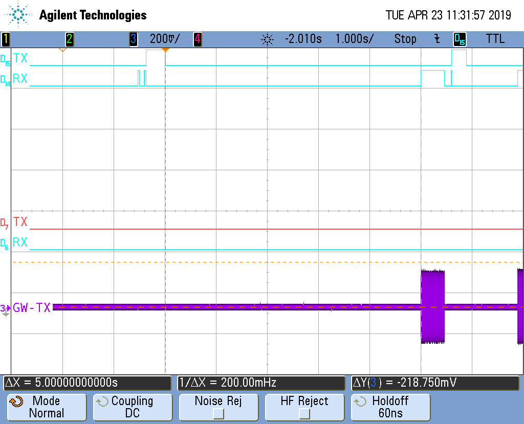
The SPI communication seems to be working. Here are some oscilloscope screenshots right after reset of the MCU with top to bottom: MISO, MOSI, SCLK, NSS
Oscilloscope screenshots


This last pic shows the whole communication with a short one after ~1.6s.

Current setup:
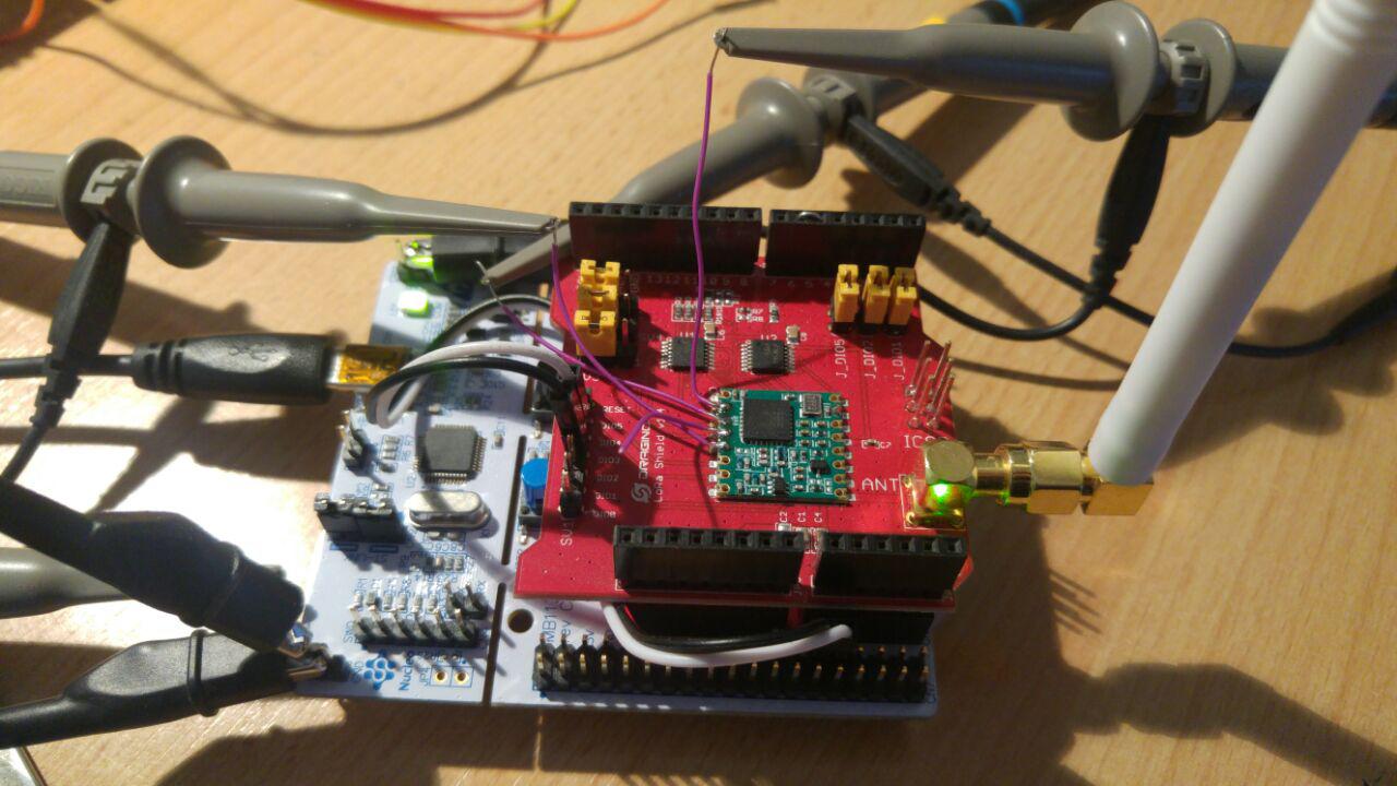
I haven’t dived deeper into the differences between the LMiC implementation and this one as I hope that someone can point me in the right direction here.
Thanks in advance!
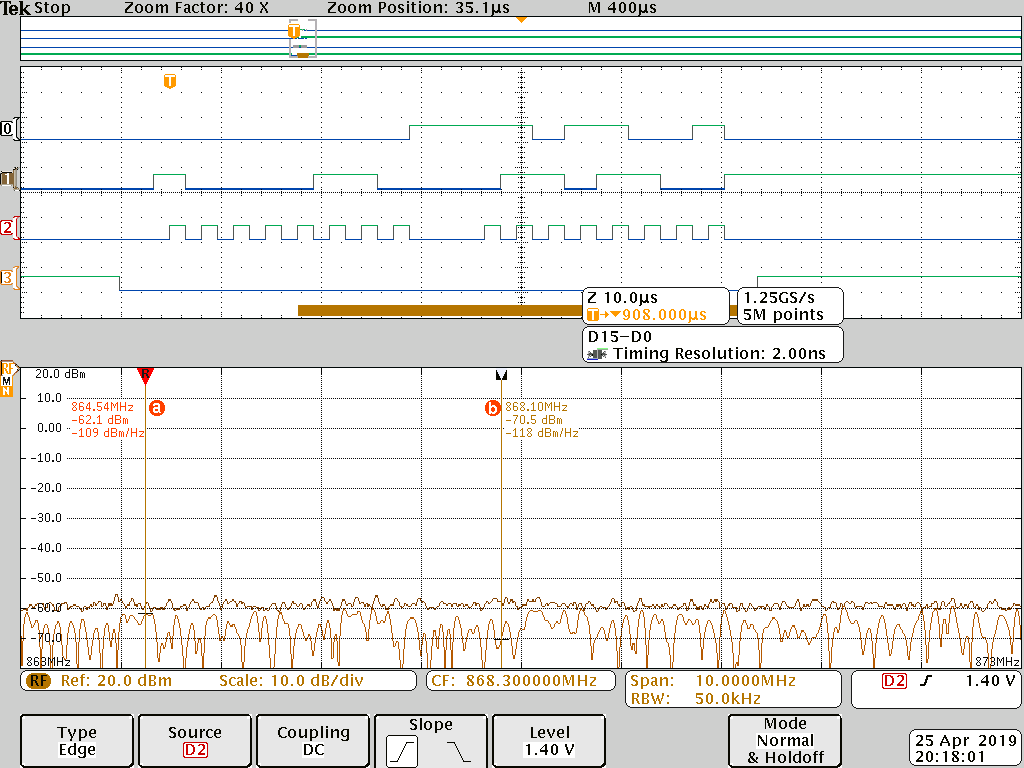
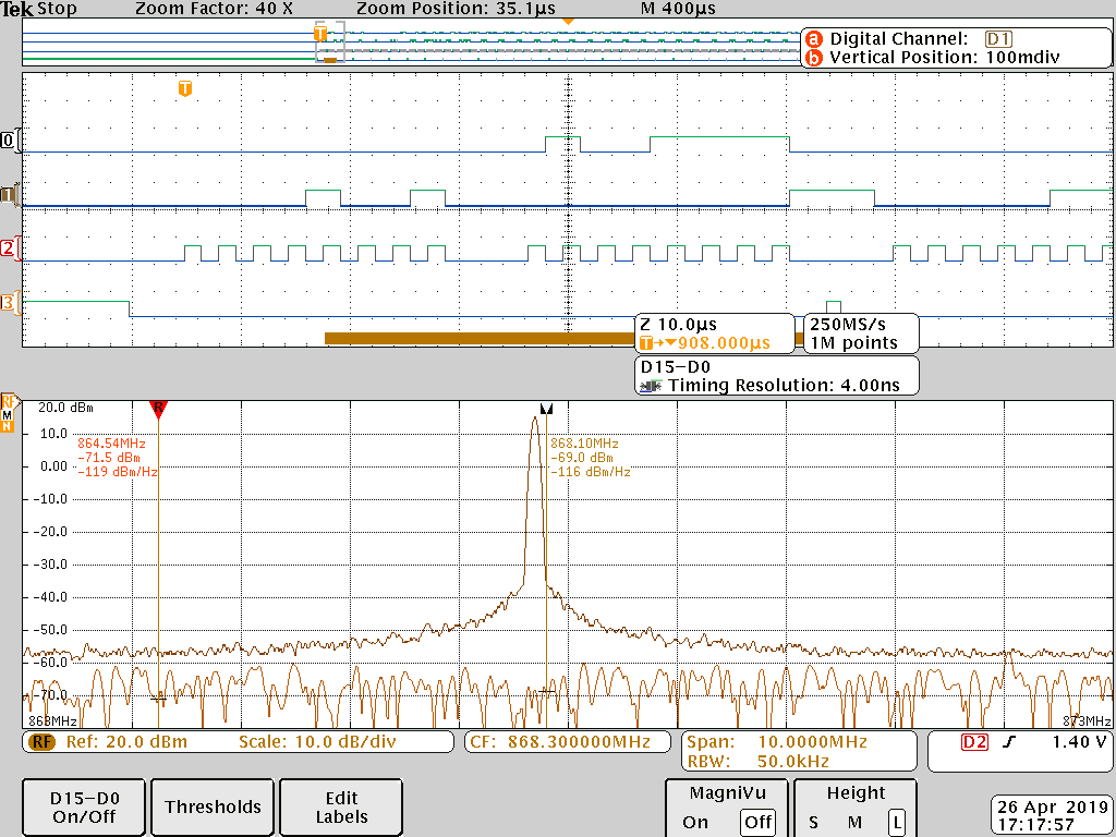
EDIT 1:
Here is another measurement with the oscilloscope. Channels 3 and 4 are now DIO0 and DIO1, which if I understand correctly are interrupts for RxDone/TxDone and TimeOut.
Apparently the DIO0 gets asserted after ~1.6s which should indicate that a packet has been transmitted and ~5s later there are two communications and assertions of DIO1.
Is this the normal behavior of the software?
DIO0 and DIO1

Configured for ABP the stack believes to send out messages successfully but there is still no traffic at the application or the gateway in the console.
This is the output of the uart:
ABP uart
###### ===== ClassA demo application v1.0.RC1 ==== ######

DevEui      : 00-07-redacted out-A7
AppEui      : 70-B3-redacted out-98-1D
AppKey      : 47 8C E2 76 redacted out B2 3A CC 3D

###### ===== JOINED ==== ######

ABP

DevAddr     : 2601110E
NwkSKey     : 1F E4 F0 59 DB redacted out 31 61 26 2B 4F
AppSKey     : EF FF 5C 7D 6A redacted out 9E F0 B2


###### ===== MCPS-Request ==== ######
STATUS      : OK

###### ===== MCPS-Confirm ==== ######
STATUS      : OK

###### ===== UPLINK FRAME 1 ==== ######

CLASS       : A

TX PORT     : 2
TX DATA     : UNCONFIRMED
00

DATA RATE   : DR_0
U/L FREQ    : 868500000
TX POWER    : 0
CHANNEL MASK: 0007


###### ===== MCPS-Request ==== ######
STATUS      : Duty-cycle restricted

###### ===== MCPS-Request ==== ######
STATUS      : Duty-cycle restricted