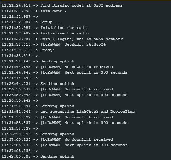
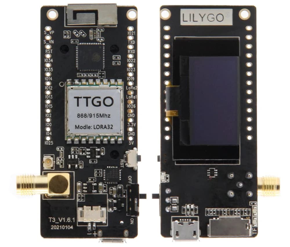
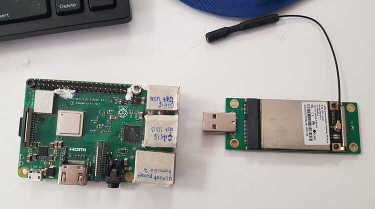
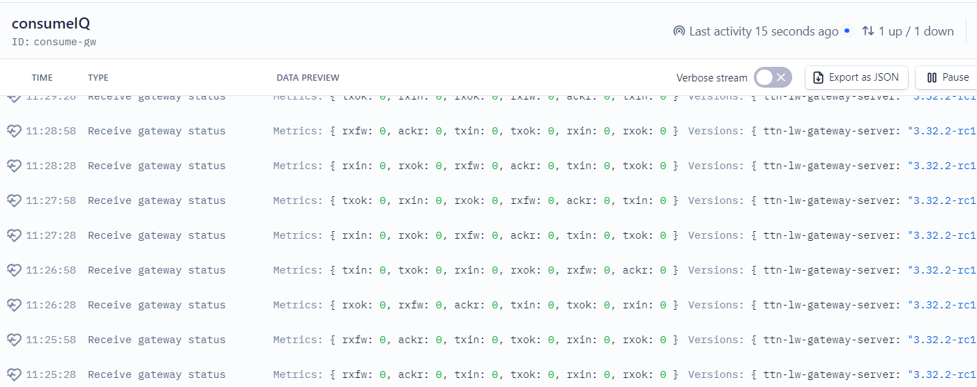
Thank you so much for your advice! I decided to reconfigure my gateway yesterday using rak_common_for_gateway, and now my end device successfully sends uplinks and receives downlinks every five minutes. My goal is to transmit PZEM004 sensor measurements to TTN. After I successfully received uplinks and downlinks from TTN today, I set up my sensor payloads according to the PZEM sensor data as follows:
function decodeUplink(input) {

  var voltage = ((input.bytes[0] << 8) | input.bytes[1]) / 100.0;
  var current = ((input.bytes[2] << 8) | input.bytes[3]) / 100.0;
  var power = ((input.bytes[4] << 8) | input.bytes[5]) / 10.0;
  var energy = ((input.bytes[6] << 8) | input.bytes[7]) / 10.0;

  return {
    data: {
      voltage: voltage,
      current: current,
      power: power,
      energy: energy
    }
  };
}
Now , my problem is I could not establish UART communication in PZEM sensor, which can be seen in PZEM-004T 100A datasheet . In the code below, I previously managed to establish UART communication with the PZEM sensor and successfully sent data over LoRa.
//PZEM
#include <PZEM004Tv30.h>
//LoRa
#include <SPI.h>
#include <LoRa.h>
//Libraries for OLED Display
#include <Wire.h>
#include <Adafruit_GFX.h>
#include <Adafruit_SSD1306.h>

#define RX_PIN 34
#define TX_PIN 25

#define SCK 5
#define MISO 19
#define MOSI 27
#define SS 18
#define RST 23
#define DIO0 26

#define BAND 866E6 //Available bandwidth for EU

//OLED pins
#define OLED_SDA 21
#define OLED_SCL 22
#define OLED_RST -1
#define SCREEN_WIDTH 128 // OLED display width, in pixels
#define SCREEN_HEIGHT 64 // OLED display height, in pixels

Adafruit_SSD1306 display(SCREEN_WIDTH, SCREEN_HEIGHT, &Wire, OLED_RST);
HardwareSerial SerialPort(1); //Note that SerialPort(0) is the USB port, which might conflict with Serial Monitor.
PZEM004Tv30 pzem(SerialPort, RX_PIN, TX_PIN);

void setup() {
  //initialize Serial Monitor
  Serial.begin(115200);
  SerialPort.begin(9600, SERIAL_8N1, RX_PIN, TX_PIN);

  //Reset OLED display via software
  pinMode(OLED_RST, OUTPUT);
  digitalWrite(OLED_RST, LOW);
  delay(20);
  digitalWrite(OLED_RST, HIGH);

  //Initialize OLED
  Wire.begin(OLED_SDA, OLED_SCL);
  if (!display.begin(SSD1306_SWITCHCAPVCC, 0x3c, false, false)) {
    Serial.println(F("SSD1306 allocation failed"));
    for (;;); // Stop, loop forever
  }

  display.clearDisplay();
  display.setTextColor(WHITE);
  display.setTextSize(1);
  display.setCursor(0,0);
  display.print("LORA PZEM SENDER");
  display.display();

  Serial.println("LoRa PZEM Test");

  //SPI LoRa pins
  SPI.begin(SCK, MISO, MOSI, SS);

  //Setup LoRa transceiver module
  LoRa.setPins(SS, RST, DIO0);

  if (!LoRa.begin(BAND)) {
    Serial.println("Starting LoRa failed!");
    while (1);
  }
  Serial.println("LoRa Initializing OK!");
  display.setCursor(0,10);
  display.print("LoRa Initializing OK!");
  display.display();
  delay(2000);
}

void loop() {
  float voltage = pzem.voltage();
  float current = pzem.current();
  float power = pzem.power();

  Serial.println("Sending Packet");

  //Send LoRa packet to receiver
  LoRa.beginPacket();
  LoRa.printf("V: %.2f V\nI: %.2f A\nP: %.2f W\n", voltage, current, power);
  LoRa.endPacket();

  // Update OLED display
  display.clearDisplay();
  display.setCursor(0,0);
  display.println("LORA SENDER");
  display.setCursor(0,10);
  display.setTextSize(1);
  display.print("PZEM SENSOR");
  display.setCursor(0,20);
  display.print("V: ");
  display.print(voltage);
  display.setCursor(0,30);
  display.print("I: ");
  display.print(current);
  display.setCursor(0,40);
  display.print("P: ");
  display.print(power);
  display.display();

  // Monitor measurements from serial
  Serial.println(voltage);
  Serial.println(current);
  Serial.println(power);

  delay(2000);
}
In this code, I’m aware that data is sent via LoRa, not LoRaWAN. However, I previously managed to get UART communication to work, but in my RadioLib_OTAA code, it fails which I could not figure out.
The RadioLib_OTAA code with PZEM integration ,
#include <PZEM004Tv30.h>
#include <RadioLib.h>
#include "LoRaBoards.h"

#define RX_PIN 34 //it is an input only pin but using it won't be a problem because it is using for only receiving.
#define TX_PIN 25

#if  defined(USING_SX1276)
SX1276 radio = new Module(RADIO_CS_PIN, RADIO_DIO0_PIN, RADIO_RST_PIN, RADIO_DIO1_PIN);
#elif defined(USING_SX1262)
SX1262 radio = new Module(RADIO_CS_PIN, RADIO_DIO1_PIN, RADIO_RST_PIN, RADIO_BUSY_PIN);
#elif defined(USING_SX1278)
SX1278 radio = new Module(RADIO_CS_PIN, RADIO_DIO0_PIN, RADIO_RST_PIN, RADIO_DIO1_PIN);
#elif   defined(USING_LR1121)
LR1121 radio = new Module(RADIO_CS_PIN, RADIO_DIO9_PIN, RADIO_RST_PIN, RADIO_BUSY_PIN);
#endif

// joinEUI - previous versions of LoRaWAN called this AppEUI
// for development purposes you can use all zeros - see wiki for details
#define RADIOLIB_LORAWAN_JOIN_EUI  0x0000000000000000


// the Device EUI & two keys can be generated on the TTN console
#ifndef RADIOLIB_LORAWAN_DEV_EUI   // Replace with your Device EUI
#define RADIOLIB_LORAWAN_DEV_EUI   0x---------------
#endif
#ifndef RADIOLIB_LORAWAN_APP_KEY   // Replace with your App Key
#define RADIOLIB_LORAWAN_APP_KEY   0x--, 0x--, 0x--, 0x--, 0x--, 0x--, 0x--, 0x--, 0x--, 0x--, 0x--, 0x--, 0x--, 0x--, 0x--, 0x--
#endif
#ifndef RADIOLIB_LORAWAN_NWK_KEY   // Put your Nwk Key here
#define RADIOLIB_LORAWAN_NWK_KEY   0x--, 0x--, 0x--, 0x--, 0x--, 0x--, 0x--, 0x--, 0x--, 0x--, 0x--, 0x--, 0x--, 0x--, 0x--, 0x--
#endif

// how often to send an uplink - consider legal & FUP constraints - see notes
const uint32_t uplinkIntervalSeconds = 5UL * 60UL;    // minutes x seconds


// for the curious, the #ifndef blocks allow for automated testing &/or you can
// put your EUI & keys in to your platformio.ini - see wiki for more tips

// regional choices: EU868, US915, AU915, AS923, IN865, KR920, CN780, CN500
const LoRaWANBand_t Region = EU868;
const uint8_t subBand = 0;  // For US915, change this to 2, otherwise leave on 0

// ============================================================================


// copy over the EUI's & keys in to the something that will not compile if incorrectly formatted
uint64_t joinEUI =   RADIOLIB_LORAWAN_JOIN_EUI;
uint64_t devEUI  =   RADIOLIB_LORAWAN_DEV_EUI;
uint8_t appKey[] = { RADIOLIB_LORAWAN_APP_KEY };
uint8_t nwkKey[] = { RADIOLIB_LORAWAN_NWK_KEY };

// create the LoRaWAN node
LoRaWANNode node(&radio, &Region, subBand);
HardwareSerial SerialPort(1); //note that SerialPort(0) is same port with Serial monitor so it will be cause code uploading errors.
PZEM004Tv30 pzem(SerialPort, RX_PIN, TX_PIN);


// result code to text - these are error codes that can be raised when using LoRaWAN
// however, RadioLib has many more - see https://jgromes.github.io/RadioLib/group__status__codes.html for a complete list
String stateDecode(const int16_t result)
{
    switch (result) {
    case RADIOLIB_ERR_NONE:
        return "ERR_NONE";
    case RADIOLIB_ERR_CHIP_NOT_FOUND:
        return "ERR_CHIP_NOT_FOUND";
    case RADIOLIB_ERR_PACKET_TOO_LONG:
        return "ERR_PACKET_TOO_LONG";
    case RADIOLIB_ERR_RX_TIMEOUT:
        return "ERR_RX_TIMEOUT";
    case RADIOLIB_ERR_CRC_MISMATCH:
        return "ERR_CRC_MISMATCH";
    case RADIOLIB_ERR_INVALID_BANDWIDTH:
        return "ERR_INVALID_BANDWIDTH";
    case RADIOLIB_ERR_INVALID_SPREADING_FACTOR:
        return "ERR_INVALID_SPREADING_FACTOR";
    case RADIOLIB_ERR_INVALID_CODING_RATE:
        return "ERR_INVALID_CODING_RATE";
    case RADIOLIB_ERR_INVALID_FREQUENCY:
        return "ERR_INVALID_FREQUENCY";
    case RADIOLIB_ERR_INVALID_OUTPUT_POWER:
        return "ERR_INVALID_OUTPUT_POWER";
    case RADIOLIB_ERR_NETWORK_NOT_JOINED:
        return "RADIOLIB_ERR_NETWORK_NOT_JOINED";
    case RADIOLIB_ERR_DOWNLINK_MALFORMED:
        return "RADIOLIB_ERR_DOWNLINK_MALFORMED";
    case RADIOLIB_ERR_INVALID_REVISION:
        return "RADIOLIB_ERR_INVALID_REVISION";
    case RADIOLIB_ERR_INVALID_PORT:
        return "RADIOLIB_ERR_INVALID_PORT";
    case RADIOLIB_ERR_NO_RX_WINDOW:
        return "RADIOLIB_ERR_NO_RX_WINDOW";
    case RADIOLIB_ERR_INVALID_CID:
        return "RADIOLIB_ERR_INVALID_CID";
    case RADIOLIB_ERR_UPLINK_UNAVAILABLE:
        return "RADIOLIB_ERR_UPLINK_UNAVAILABLE";
    case RADIOLIB_ERR_COMMAND_QUEUE_FULL:
        return "RADIOLIB_ERR_COMMAND_QUEUE_FULL";
    case RADIOLIB_ERR_COMMAND_QUEUE_ITEM_NOT_FOUND:
        return "RADIOLIB_ERR_COMMAND_QUEUE_ITEM_NOT_FOUND";
    case RADIOLIB_ERR_JOIN_NONCE_INVALID:
        return "RADIOLIB_ERR_JOIN_NONCE_INVALID";
    case RADIOLIB_ERR_N_FCNT_DOWN_INVALID:
        return "RADIOLIB_ERR_N_FCNT_DOWN_INVALID";
    case RADIOLIB_ERR_A_FCNT_DOWN_INVALID:
        return "RADIOLIB_ERR_A_FCNT_DOWN_INVALID";
    case RADIOLIB_ERR_DWELL_TIME_EXCEEDED:
        return "RADIOLIB_ERR_DWELL_TIME_EXCEEDED";
    case RADIOLIB_ERR_CHECKSUM_MISMATCH:
        return "RADIOLIB_ERR_CHECKSUM_MISMATCH";
    case RADIOLIB_ERR_NO_JOIN_ACCEPT:
        return "RADIOLIB_ERR_NO_JOIN_ACCEPT";
    case RADIOLIB_LORAWAN_SESSION_RESTORED:
        return "RADIOLIB_LORAWAN_SESSION_RESTORED";
    case RADIOLIB_LORAWAN_NEW_SESSION:
        return "RADIOLIB_LORAWAN_NEW_SESSION";
    case RADIOLIB_ERR_NONCES_DISCARDED:
        return "RADIOLIB_ERR_NONCES_DISCARDED";
    case RADIOLIB_ERR_SESSION_DISCARDED:
        return "RADIOLIB_ERR_SESSION_DISCARDED";
    }
    return "See https://jgromes.github.io/RadioLib/group__status__codes.html";
}

// helper function to display any issues
void debug(bool failed, const __FlashStringHelper *message, int state, bool halt)
{
    if (failed) {
        Serial.print(message);
        Serial.print(" - ");
        Serial.print(stateDecode(state));
        Serial.print(" (");
        Serial.print(state);
        Serial.println(")");
        while (halt) {
            delay(1);
        }
    }
}

// helper function to display a byte array
void arrayDump(uint8_t *buffer, uint16_t len)
{
    for (uint16_t c = 0; c < len; c++) {
        char b = buffer[c];
        if (b < 0x10) {
            Serial.print('0');
        }
        Serial.print(b, HEX);
    }
    Serial.println();
}


void setup()
{
    Serial.begin(115200);
    while (!Serial);

    setupBoards();

#ifdef  RADIO_TCXO_ENABLE
    pinMode(RADIO_TCXO_ENABLE, OUTPUT);
    digitalWrite(RADIO_TCXO_ENABLE, HIGH);
#endif

    delay(5000);  // Give time to switch to the serial monitor

    Serial.println(F("\nSetup ... "));

    Serial.println(F("Initialise the radio"));

    int16_t state = 0;  // return value for calls to RadioLib
    Serial.println(F("Initialise the radio"));
    state = radio.begin();
    debug(state != RADIOLIB_ERR_NONE, F("Initialise radio failed"), state, true);

#ifdef USING_DIO2_AS_RF_SWITCH
#ifdef USING_SX1262
    // Some SX126x modules use DIO2 as RF switch. To enable
    // this feature, the following method can be used.
    // NOTE: As long as DIO2 is configured to control RF switch,
    //       it can't be used as interrupt pin!
    if (radio.setDio2AsRfSwitch() != RADIOLIB_ERR_NONE) {
        Serial.println(F("Failed to set DIO2 as RF switch!"));
        while (true);
    }
#endif //USING_SX1262
#endif //USING_DIO2_AS_RF_SWITCH

#ifdef RADIO_SWITCH_PIN
    // T-MOTION
    const uint32_t pins[] = {
        RADIO_SWITCH_PIN, RADIO_SWITCH_PIN, RADIOLIB_NC,
    };
    static const Module::RfSwitchMode_t table[] = {
        {Module::MODE_IDLE,  {0,  0} },
        {Module::MODE_RX,    {1, 0} },
        {Module::MODE_TX,    {0, 1} },
        END_OF_MODE_TABLE,
    };
    radio.setRfSwitchTable(pins, table);
#endif

#if  defined(USING_LR1121)
    // LR1121
    // set RF switch configuration for Wio WM1110
    // Wio WM1110 uses DIO5 and DIO6 for RF switching
    static const uint32_t rfswitch_dio_pins[] = {
        RADIOLIB_LR11X0_DIO5, RADIOLIB_LR11X0_DIO6,
        RADIOLIB_NC, RADIOLIB_NC, RADIOLIB_NC
    };

    static const Module::RfSwitchMode_t rfswitch_table[] = {
        // mode                  DIO5  DIO6
        { LR11x0::MODE_STBY,   { LOW,  LOW  } },
        { LR11x0::MODE_RX,     { HIGH, LOW  } },
        { LR11x0::MODE_TX,     { LOW,  HIGH } },
        { LR11x0::MODE_TX_HP,  { LOW,  HIGH } },
        { LR11x0::MODE_TX_HF,  { LOW,  LOW  } },
        { LR11x0::MODE_GNSS,   { LOW,  LOW  } },
        { LR11x0::MODE_WIFI,   { LOW,  LOW  } },
        END_OF_MODE_TABLE,
    };
    radio.setRfSwitchTable(rfswitch_dio_pins, rfswitch_table);

    // LR1121 TCXO Voltage 2.85~3.15V
    radio.setTCXO(3.0);
#endif

    // Override the default join rate
    uint8_t joinDR = 4;

    // Setup the OTAA session information
    node.beginOTAA(joinEUI, devEUI, nwkKey, appKey);

    Serial.println(F("Join ('login') the LoRaWAN Network"));
    state = node.activateOTAA(joinDR);
    debug(state != RADIOLIB_LORAWAN_NEW_SESSION, F("Join failed"), state, true);

    // Print the DevAddr
    Serial.print("[LoRaWAN] DevAddr: ");
    Serial.println((unsigned long)node.getDevAddr(), HEX);

    // Enable the ADR algorithm (on by default which is preferable)
    node.setADR(true);

    // Set a datarate to start off with
    node.setDatarate(5);

    // Manages uplink intervals to the TTN Fair Use Policy
    node.setDutyCycle(true, 1250);

    // Enable the dwell time limits - 400ms is the limit for the US
    node.setDwellTime(true, 400);

    Serial.println(F("Ready!\n"));

    if (u8g2) {
        u8g2->clearBuffer();
        u8g2->setFont(u8g2_font_NokiaLargeBold_tf );
        uint16_t str_w =  u8g2->getStrWidth(BOARD_VARIANT_NAME);
        u8g2->drawStr((u8g2->getWidth() - str_w) / 2, 16, BOARD_VARIANT_NAME);
        u8g2->drawHLine(5, 21, u8g2->getWidth() - 5);

        u8g2->setCursor(0, 38);
        u8g2->print("Join LoRaWAN Ready!");
        u8g2->sendBuffer();
    }
}


void loop()
{
    int16_t state = RADIOLIB_ERR_NONE;

    // set battery fill level - the LoRaWAN network server
    // may periodically request this information
    // 0 = external power source
    // 1 = lowest (empty battery)
    // 254 = highest (full battery)
    // 255 = unable to measure
    uint8_t battLevel = 146;
    node.setDeviceStatus(battLevel);

     // This is the place to gather the sensor inputs
    float voltage = pzem.voltage();
    float current = pzem.current();
    float power = pzem.power();
    float energy = pzem.energy();

     // Build payload byte array
    uint8_t uplinkPayload[8];
    uplinkPayload[0] = (uint16_t)(voltage * 100) >> 8;      // V (high byte)
    uplinkPayload[1] = (uint16_t)(voltage * 100) & 0xFF;    // V(low byte)
    uplinkPayload[2] = (uint16_t)(current * 100) >> 8;      // I (high byte)
    uplinkPayload[3] = (uint16_t)(current * 100) & 0xFF;    // I (low byte)
    uplinkPayload[4] = (uint16_t)(power * 10) >> 8;         // P (high byte)
    uplinkPayload[5] = (uint16_t)(power * 10) & 0xFF;       // P (low byte)
    uplinkPayload[6] = (uint16_t)(energy * 10) >> 8;        // E (high byte)
    uplinkPayload[7] = (uint16_t)(energy * 10) & 0xFF;      // E (low byte)


    uint8_t downlinkPayload[10];  // Make sure this fits your plans!
    size_t  downlinkSize;         // To hold the actual payload size received

    // you can also retrieve additional information about an uplink or
    // downlink by passing a reference to LoRaWANEvent_t structure
    LoRaWANEvent_t uplinkDetails;
    LoRaWANEvent_t downlinkDetails;

    uint8_t fPort = 10;

    // Retrieve the last uplink frame counter
    uint32_t fCntUp = node.getFCntUp();

    // Send a confirmed uplink on the second uplink
    // and also request the LinkCheck and DeviceTime MAC commands
    Serial.println(F("Sending uplink"));
    if (fCntUp == 1) {
        Serial.println(F("and requesting LinkCheck and DeviceTime"));
        node.sendMacCommandReq(RADIOLIB_LORAWAN_MAC_LINK_CHECK);
        node.sendMacCommandReq(RADIOLIB_LORAWAN_MAC_DEVICE_TIME);
        state = node.sendReceive(uplinkPayload, sizeof(uplinkPayload), fPort, downlinkPayload, &downlinkSize, true, &uplinkDetails, &downlinkDetails);
    } else {
        state = node.sendReceive(uplinkPayload, sizeof(uplinkPayload), fPort, downlinkPayload, &downlinkSize, false, &uplinkDetails, &downlinkDetails);
    }
    debug(state < RADIOLIB_ERR_NONE, F("Error in sendReceive"), state, false);

    // Check if a downlink was received
    // (state 0 = no downlink, state 1/2 = downlink in window Rx1/Rx2)
    if (state > 0) {
        Serial.println(F("Received a downlink"));
        // Did we get a downlink with data for us
        if (downlinkSize > 0) {
            Serial.println(F("Downlink data: "));
            arrayDump(downlinkPayload, downlinkSize);
        } else {
            Serial.println(F("<MAC commands only>"));
        }

        // print RSSI (Received Signal Strength Indicator)
        Serial.print(F("[LoRaWAN] RSSI:\t\t"));
        Serial.print(radio.getRSSI());
        Serial.println(F(" dBm"));

        // print SNR (Signal-to-Noise Ratio)
        Serial.print(F("[LoRaWAN] SNR:\t\t"));
        Serial.print(radio.getSNR());
        Serial.println(F(" dB"));

        // print extra information about the event
        Serial.println(F("[LoRaWAN] Event information:"));
        Serial.print(F("[LoRaWAN] Confirmed:\t"));
        Serial.println(downlinkDetails.confirmed);
        Serial.print(F("[LoRaWAN] Confirming:\t"));
        Serial.println(downlinkDetails.confirming);
        Serial.print(F("[LoRaWAN] Datarate:\t"));
        Serial.println(downlinkDetails.datarate);
        Serial.print(F("[LoRaWAN] Frequency:\t"));
        Serial.print(downlinkDetails.freq, 3);
        Serial.println(F(" MHz"));
        Serial.print(F("[LoRaWAN] Frame count:\t"));
        Serial.println(downlinkDetails.fCnt);
        Serial.print(F("[LoRaWAN] Port:\t\t"));
        Serial.println(downlinkDetails.fPort);
        Serial.print(F("[LoRaWAN] Time-on-air: \t"));
        Serial.print(node.getLastToA());
        Serial.println(F(" ms"));
        Serial.print(F("[LoRaWAN] Rx window: \t"));
        Serial.println(state);

        uint8_t margin = 0;
        uint8_t gwCnt = 0;
        if (node.getMacLinkCheckAns(&margin, &gwCnt) == RADIOLIB_ERR_NONE) {
            Serial.print(F("[LoRaWAN] LinkCheck margin:\t"));
            Serial.println(margin);
            Serial.print(F("[LoRaWAN] LinkCheck count:\t"));
            Serial.println(gwCnt);
        }

        uint32_t networkTime = 0;
        uint8_t fracSecond = 0;
        if (node.getMacDeviceTimeAns(&networkTime, &fracSecond, true) == RADIOLIB_ERR_NONE) {
            Serial.print(F("[LoRaWAN] DeviceTime Unix:\t"));
            Serial.println(networkTime);
            Serial.print(F("[LoRaWAN] DeviceTime second:\t1/"));
            Serial.println(fracSecond);
        }

    } else {
        Serial.println(F("[LoRaWAN] No downlink received"));
    }

    // wait before sending another packet
    uint32_t minimumDelay = uplinkIntervalSeconds * 1000UL;
    uint32_t interval = node.timeUntilUplink();     // calculate minimum duty cycle delay (per FUP & law!)
    uint32_t delayMs = max(interval, minimumDelay); // cannot send faster than duty cycle allows

    Serial.print(F("[LoRaWAN] Next uplink in "));
    Serial.print(delayMs / 1000);
    Serial.println(F(" seconds\n"));

    delay(delayMs);
}
When I commented out all sections in the loop() except for PZEM readings, such as float voltage = pzem.voltage(); and Serial.println(voltage);, UART communication with the sensor seems to work fine.
The issue appears to stem from something in the setup() section. I know it’s unreasonable to expect anyone to find the exact line causing the issue, but your suggestions have been very valuable to me. Thank you very much for the help and insights you’ve provided so far.
 (2)
(2)
 (3)
(3) (4)
(4)
