Hope RFM95/98 power usage in sleep mode?

Guys,

I faced this kind of problem when played with ULPNode, In my case I was powering down RFM module with a mosfet to be sure 0 power will be consumed but had problem with port config pull up/down, I solved with the following code

The one part interesting for you is the part after f (!power)

/* ======================================================================
Function: powerRadio
Purpose : expose driver method of power or unpower the RF module 
Input   : true to power on false to power off
Output  : true if powered and module found
Comments: -
====================================================================== */
boolean ULPNode::powerRadio(uint8_t power)
{

  // do we need to power up the sensors
  if ( power) {
    uint8_t status_mask = 0;

    // From here and with latest Arduino version we have a problem
    // Arduino SPI library now check if SPI has already been initialized
    // if so, init is not done again and as we changed SS pin and some 
    // others to have full Low Power, we need to enhance back all as it
    // should be done in a real Spi init EACH time.
  
    //SPCR |= _BV(SPE);

    // Warning: if the SS pin ever becomes a LOW INPUT then SPI
    // automatically switches to Slave, so the data direction of
    // the SS pin MUST be kept as OUTPUT.

    // set back CSN pin with pullup (it was input)
    digitalWrite(RF_CSN_PIN, HIGH); 
    // now set it as output high
    pinMode(RF_CSN_PIN, OUTPUT); 
    digitalWrite(RF_CSN_PIN, HIGH); 

    // Power Up Modules SPI 
    power_spi_enable();  

    // Enable back SPI and set as MASTER
    SPCR |= _BV(SPE);
    SPCR |= _BV(MSTR);

    // MISO pin automatically overrides to INPUT.
    // By doing this AFTER enabling SPI, we avoid accidentally
    // clocking in a single bit since the lines go directly
    // from "input" to SPI control.
    // http://code.google.com/p/arduino/issues/detail?id=888
    // Not needed because we didn't changed these pins 
    //pinMode(SCK, OUTPUT);
    //pinMode(MOSI, OUTPUT);

    // power ON VCC the radio module
    setDevice(DEVICE_RF_ON);

    // RF module settle delay 
    sleepQuickWake( WDTO_15MS );
    //delay(15);

    if (_radio_type == RF_MOD_NRF24)
      status_mask = RF_NODE_STATE_NRF24;
    if (_radio_type == RF_MOD_RFM69)
      status_mask = RF_NODE_STATE_RFM69;

    // Init the radio driver with moteino config
    if (!driver.init()) {
      // Radio state not OK
      _status &= ~status_mask;
      return false;
    }

    // Radio is okay
    _status |= status_mask;

    // Specific init for RFM69
    if ( _status & RF_NODE_STATE_RFM69) {
      RH_RF69 * prf69_drv = (RH_RF69 *) &driver;

      // Moteino settings
      prf69_drv->setModemConfig(RH_RF69::FSK_MOTEINO);
      prf69_drv->setPreambleLength(3);
      // Copied from LowPowerLab 
      prf69_drv->spiWrite(RH_RF69_REG_29_RSSITHRESH, 220);
      prf69_drv->spiWrite(RH_RF69_REG_3D_PACKETCONFIG2, RH_RF69_PACKETCONFIG2_RXRESTARTDELAY_2BITS | RH_RF69_PACKETCONFIG2_AUTORXRESTARTON);

      // default moteino Frequency For 433 MHz 
      prf69_drv->setFrequency(433.0);
    }

    // Specific init for NRF24
    if ( _status & RF_NODE_STATE_NRF24) {
      // Defaults after init are 2.402 GHz (channel 2), 2Mbps, 0dBm
      //nrf24.setChannel(1))
      //nrf24.setRF(RH_NRF24::DataRate2Mbps, RH_NRF24::TransmitPower0dBm))
    }
  }
  
  // So this is a power off
  if ( !power) {
    // This will configure the radio pins for correct low power mode
    driver.sleep();

    // We're going to sleep, we've done our job no need to be awake by
    // RF module firing up a IRQ when we're in power down (can cause trouble?)
    //detachInterrupt(digitalPinToInterrupt(RF_IRQ_PIN));

    // Once agin, very important even if we power off the module, because 
    // of pullup, module still powered via SS/IRQ Pin. if we don't do this
    // even if VDD of RFModule set to "float" using mosfet, current is get
    // drawn by other pins pullup (CS or IRQ), so disable pull up
    pinMode(RF_CSN_PIN, INPUT); 
    digitalWrite(RF_CSN_PIN, 0); 

    // Disable SPI device
    SPCR &= ~_BV(SPE);
    
    // unpower SPI of Arduino
    power_spi_disable();  

    // unpower RF module
    setDevice(DEVICE_RF_OFF);
  }

  return (true);
}  
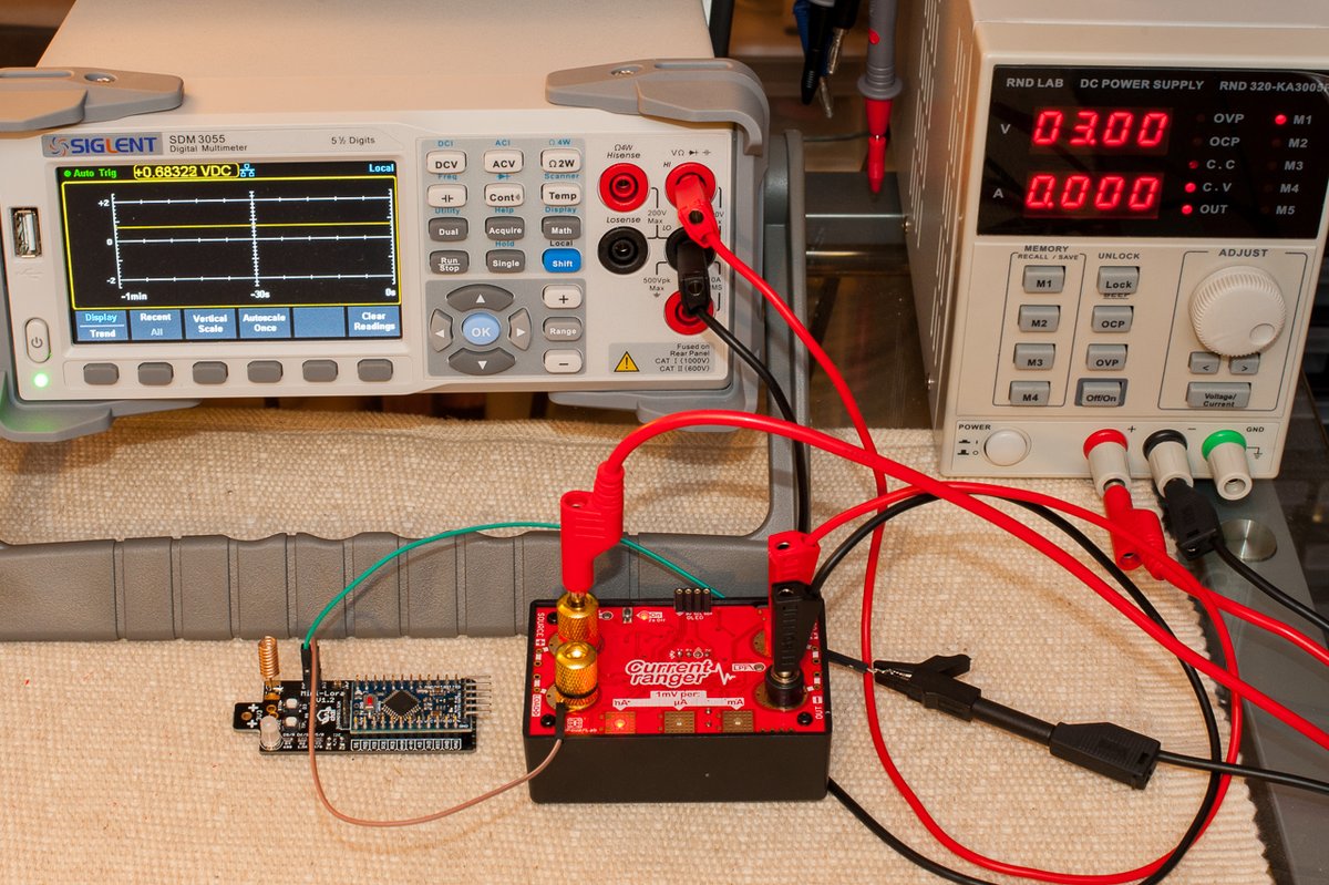

And for those interested here the code to disable all ATMega328 device for low power

Remember that I power down devices (I2C and SPI) using a mosfet to enable/disable them so all VDD pin of devices is then left float

/* ======================================================================
Function: disableCPUDevices
Purpose : disable Atmel integrated devices (for low power)
Input   : -
Output  : - 
Comments: - 
====================================================================== */
void ULPNode::disableCPUDevices(void)
{
  // Disable ADC 
  ADCSRA &= ~_BV(ADEN)  ; 

  // disable Analog comparator  
  ACSR |= _BV(ACD); 
  
  // Disable digital input buffers on all ADC0-ADC5 pins
  //DIDR0 = 0x3F;    

  // set I2C pin as input no pull up
  // this prevent current draw on I2C pins that
  // completly destroy our low power mode

  //Disable I2C interface so we can control the SDA and SCL pins directly
  TWCR &= ~(_BV(TWEN)); 

  // disable I2C module this allow us to control
  // SCA/SCL pins and reinitialize the I2C bus at wake up
  TWCR = 0;
  pinMode(SDA, INPUT);
  pinMode(SCL, INPUT);
  digitalWrite(SDA, LOW);
  digitalWrite(SCL, LOW);  

  /*
  power_adc_disable();
  power_usart0_disable();
  power_spi_disable();  
  power_twi_disable();
  power_timer0_disable(); 
  power_timer1_disable();
  power_timer2_disable();
  */

  power_all_disable();
}
2 Likes

Even easier to minimize power use during sleep mode is to define unused IO pins as output (commonly used on ATmega/‘Arduino’).

23 posts were merged into an existing topic: Big STM32 boards topic

@BoRRoZ @everyone

I think the STM32 related posts should be placed in the Big STM32 boards topic
Maybe above STM32 posts can be moved to the STM32 topic (where they are easier to find and don’t hijack this topic).

1 Like

done… let’s keep this topic for the RFM95/98.

I stumbled across this conversation about enabeling the PA_BOOST to have +20dBm

1 Like

I tried to combine deepsleep of atmega328 and RFM95 controlled via LMIC library.

  • at first i do a JOIN to the LoraWAN nework and store the session information in RAM
  • after an initial data send i put the CPU to deepsleep via
    LowPower.powerDown(SLEEP_8S, ADC_OFF, BOD_OFF);
  • then i call
    LMIC_shutdown();
  • every nth wakeup i call
    LMIC_reset();
  • and recall the last session settings via
    LMIC_setSession (netid, devaddr, nwkKey, artKey);
  • additionally i set the same parameters as i did in EV_JOINED event
    LMIC_setClockError(MAX_CLOCK_ERROR * 1 / 100); //Relax RX timing window
    LMIC_setAdrMode(1); //enable ADR
    LMIC_setLinkCheckMode(1);
    LMIC_setDrTxpow(DR_SF9, 15);
  • finally i trigger a new packet via
    os_setCallback(…)

So far this seems to work well, but there is a question left: is the sequence
LMIC_setClockError(MAX_CLOCK_ERROR * 1 / 100); //Relax RX timing window
LMIC_setAdrMode(1); //enable ADR
LMIC_setLinkCheckMode(1);
LMIC_setDrTxpow(DR_SF9, 15);

to much, or do i need to set additional parameters?

The question might sound stupid because it seems to work fine, but i want to be on the safe side…

1 Like
  • I never shutdown/reset LMIC while sleeping (or save anything from the session)…
  • LMIC_setDrTxpow(DR_SF9, 15): there is probably no point of setting Data Rate if you do ADR; also if you are in Europe, 14dBm is the maximum you can use (It is not important as LMIC doesn’t do anything with that anyway)
1 Like

So, have you measured your power consumption with/without shutdown?
If I have not done a mistake there was a significant difference!

I have not, less than 0.7 µA was good enough for me…

1 Like

Hi,

I’m now using the MSP430 and RFM95. When I was testing the total current of the whole system. I put RFM95 into sleep and put MSP430 pin’s output low. The system cost 0.5mA which is much high. What I’m sure of is that MSP430 cost only a few uA. I also guess the DIO cost some power. But I didn’t find anything in the datasheet to configure the DIO.
If anyone can help, that will be so grateful.

1 Like

Hey i am currently trying to use msp430 and rfm98 for data transmission and i am kinda stuck so can you please help me by sending your code and the library you are using for rfm98 module

Hello everyone. I bought a diycon V2.03 and run an rfm95 on it. a dth22 is also installed. I tried various things to reduce electricity consumption. unfortunately i am not a professional programmer and my english google translate.
I wanted to try that with that

Solution 1:
Setting the SPI and other pins with the following code did the rest:

digitalWrite (PA5, LOW); // SCK
pinMode (PA5, OUTPUT);

digitalWrite (PA7, LOW); // MOSI
pinMode (PA7, OUTPUT);

pinMode (PA6, INPUT_ANALOG); // MISO

digitalWrite (lmic_pins.nss, LOW); // NSS
pinMode (lmic_pins.nss, OUTPUT);

// DIO inputs
pinMode (PA3, INPUT_ANALOG);
pinMode (PB5, INPUT_ANALOG);

pinMode (lmic_pins.rst, INPUT_ANALOG);

// Serial
pinMode (PA9, INPUT_ANALOG);
pinMode (PA10, INPUT_ANALOG);

Problem 1:
Unfortunately I do not find a PA1…PA7 there is always an error when compiling
Unfortunately I don’t know what is meant by rewrapping and pulling up: _ (

Solution 2:
I use Freescale excuse me NXP Kinetis MK20 controllers, which are based on the same Cortex cores as the STM32, together with this excellent library 63 for very satisfying results. The library saves the pin state, then puts all pins to output low and goes to sleep. When it wakes again, pin state is restored and the program continues as if nothing happened. The controller uses around 15µA during sleep.

Problem 2:
There is always an error message here. I saw that it is not an Arduino board: _ /

Could someone help me?

Which library for the RFM95 are you using ?

There are software mechanisms for putting the RFM95 into a sub 1uA sleep.

Hi Schallb, Could you send me a example using LowPower.powerDown(SLEEP_8S, ADC_OFF, BOD_OFF); combinated with LMIC_shutdown();
I having dificult to put the RFm95w to starting working again after deep sleep. Thanks

In TinyLoRa I re-issue lora.setChannel();lora.setDataRate();lora.begin();lora.setPower(); after deep sleep. I don’t know about LMIC, but I suppose something similar like i see here.

I think you need after deep sleep
os_init();
/ Reset the MAC state. Session and pending data transfers will be discarded.
LMIC_reset();
LMIC_setLinkCheckMode(0);
LMIC_setDrTxpow(DR_SF7,14);
LMIC_selectSubBand(1);

Right, i have following sequence after wakeup:
LMIC_reset();
RestoreSettings(&otaa_data);

where RestoreSettings does:
LMIC.dn2Dr = DR_SF9;
LMIC_setSession((*data).netid, (*data).devaddr, (xref2u1_t)(*data).nwkKey, (xref2u1_t)(*data).artKey);
LMIC_setSeqnoUp((*data).seqnoUp);
LMIC_setDrTxpow((*data).datarate, (*data).adrTxPow);
LMIC_setAdrMode((*data).adrEnabled); //enable ADR

Thanks Charles, it helps me a lot. Now it is finally working with LMIC library. 0.4uA sleep mode. I need to use MAX6817 (~2.6uA) in two switches inputs because each have long cables to a float switch sensor so the total consumption in sleep mode is about 3uA. Measuring the battery voltage with this technique (https://jeelabs.org/2013/05/18/zero-power-measurement-part-2/index.html). Switching the RF with a P-Mosfet (0A in sleep mode).

It has been a while (4 years: See Hope RFM95/98 power usage in sleep mode? - #18 by tomtor ), but my old STM32 code example can be reduced to:

  pinMode(PA6, INPUT_ANALOG); // MISO, from 0.5 to 0.06mA (regulator current)!

  // Serial:
  pinMode(PA9, INPUT_ANALOG);
  pinMode(PA10, INPUT_ANALOG);

The MISO line was my main issue.

Setting the serial lines has less impact.

After the deep sleep I resume with:

Serial.begin(115200);
SPIp->begin();