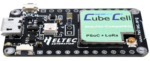
Can anyone who is more experienced with the Heltec Cubecell AB01 board tell me which pins I can use for analogRead() from a sensor?
My sensor output is 0-5 volt, do I need to reduce this to 0-3.3 volt?

Can anyone who is more experienced with the Heltec Cubecell AB01 board tell me which pins I can use for analogRead() from a sensor?
My sensor output is 0-5 volt, do I need to reduce this to 0-3.3 volt?

Jason from Heltec was so kind to answer: max input on pin 2 (ADC/Power Detection) is 3.7 volt.
You’ll need a resistor divider to ensure you bring your 5V down to below 3.7V proportionally
Thanks, I’ll use it 
Hi, HansJJ. Could you resolve your problem? I try to read an analog soil moisture sensor (soilwatch 10), I use de ADC pin to read the values, but the reading doesn´t change. Do you have any code example that can be useful for me? Thanks
Hi everyone. I try to read an analog soil moisture sensor (soilwatch 10), I use the ADC pin to read the values, but the reading doesn´t change. Do you know why does this happen?
I read here: HELTEC DOCS " ADC input pin had been used for battery voltage reading default." “In order to read other analog signal, user need remove the resistance BR1, then the ADC header will be free”
Is that correct? I think it’s impractical for any purpose of reading analog sensors. Or maybe I don’t understand what they’re saying.
Here a basic code example I used
void setup() {
	Serial.begin(115200);
  	pinMode(ADC, INPUT);
}
void loop() {
	int voltage= analogRead(ADC);
	Serial.print("ADC = " );
  	Serial.println(voltage);
	delay(1500);
}
Please do not double post or start a new topic - it splits the efforts of the people answering, all volunteers.
Sorry for that. But the doubt to my query still persists. I already tried what was discussed in this topic.
Understand, you’ll have to be patient and see if anyone knows the answer.
Assuming you have removed the resistor as per the Heltec instructions, can you link to the documentation for the sensor and tell us how you have wired it up.
The most basic test to try would be to get a couple of similar value resistors, put one between 3V3 & ADC and the other between the ADC and Gnd.
At face value the code looks OK.
I see the question differently.
Unfortunately, it really seems that there is only one input for analog on the module and it is occupied with VBat.
Thanks for the question, I had overlooked that until now.
The tip to disconnect the but contradicts the possibility to see how high the battery voltage is, which I can use in my application small weather station well gebrauchenm, because the mini solar cell that supplies the battery with voltage also shows whether sun shines or not. If I could possibly need more analog inputs I would use an ADS1115 ADC module in that case and would have additional 4 channels with 16bit resolution. If the module is connected via vext it does not need power during a deep sleep.
Translated with DeepL Translate: The world's most accurate translator (free version) from
Ich sehe die Fragestellung anders.
Leider scheint es wirklich so zu sein, dass es auf dem Modul nur einen Eingang für Analog hat und der mit VBat belegt ist.
Danke für die Frage, das hatte ich bisher übersehen.
Der Tip den abzuklemmen widerspricht aber der Möglichkeit zu sehen wie hoch die Akkuspannung ist, was ich in meiner Applikation kleine Wetterstation gut gebrauchen kannm, denn die Minisolarzelle die den Akku mit Spannung versorgt zeigt auch ob Sonne scheint oder nicht. Wenn ich eventuell weitere Analogeingänge brauchen könnte würde ich in dem Fall einen ADS1115 ADC Modul nutzen und hätte zusätzlich 4 Kanäle mit 16bit Auflösung. Wenn Das Modul über vext angeschlossen wird benötigt es keinen Strom während eines Deep-Sleep.
OK, minor thread hijack as not strictly relevant to the issue at hand, but good point.
I’d also recommend the MCP3008 - it’s SPI, 8 channel, 10 bit which is usually more than enough for such things.
I would also recommend the MCP3008 - it’s SPI, 8 channel, 10 bit, which is usually more than enough for this sort of thing.
I don’t think SPI is right for the CubeCell boards. The Lora module is already connected to the SPI bus - I don’t think there is a second one like on the ESP32.
Therefore I would prefer the I2C bus. $ analog inputs should be enough. Maximum 16 inputs could be connected with 4 modules, because 4 addresses are selectable.
The ADS1115 ADC would then even have the advantage of triggering an interrupt when it continues to measure with voltage when parameterized limits are exceeded, and to wake up the processor in deep sleep.
Otherwise you are right, I have also only an example given which I had chosen in the question.
There gint also the possibility to take the Heltec HTCC-AB02, which has 3 analog inputs. So that then 2 free analog signals are possible in addition to the battery voltage.