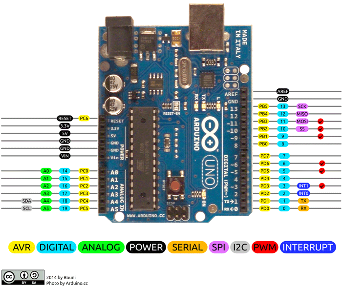
I have a Dragino lora shield v1.4 running on an arduino with a DHT11 temp/humidity sensor. It is sending data to my dragino gateway LG01. I’am running the basic arduino sketches (lora_simple_gateway_DHT11 / lora_simple_client_DHT11). It is working fine when powering the Arduino with usb (my computer). I do receive packets on my gateway and I can see true values for temp and humidity. However when powering the arduino with an external power supply, I still receive packets but with zero values for temp/humidity. Somehow it seems DHT11 won’t work when it is not powered over usb. My first thought was to disable serial communication in my arduino sketch, but this did no do the trick. Does anyone have a suggestion? What can be the difference between usb powered vs external power supply? Thanks
did you meassure if the DHT11 gets power in the 'usb situation
It’s seem that when the arduino is with external power supply, the voltage isn’t sufficient for the DHT11. I think that you should measure voltage out of power supply, normally is recommended 7 to 12 VDC.
The external power supply is 12V/1.0A. The DHT11 is connected to the 5V pin on the Arduino with a 10k resistor between the 5V and the analog pin A0. So i’am pretty sure it has nothing to do with sufficient powering of the sensor.
In the meantime I have commented out the ‘Serial.begin(9600)’ in the arduino sketch and replaced serial connection with <SoftwareSerial.h>. I hooked pin 3 and 4 on the arduino to a UART to usb converter so I can monitor serial communication without having to plug in the usb port of the Arduino in my computer.
Now I have exactly the same problem. When powering up the Arduino when I have my UART to usb converter up and running, I get sensor values. When powering up the arduino without monitoring serial communication it returns zero values. When I plug the UART to usb converter afterwards, I see in my serial communication that it has failed to initialize the sensor. Somehow I suspect a timing problem while initializing the DHT11 sensor when there is no serial communication.
Below is part of the sketch which initialises the DHT11 (the bGlobalErr=1 returns the serial message ‘Error 1: DHT start condition 1 not met’)
digitalWrite(dht_dpin,LOW);//Pull Low A0 and send signal
delay(30);//Delay > 18ms so DHT11 can get the start signal
digitalWrite(dht_dpin,HIGH);
delayMicroseconds(40);//Check the high level time to see if the data is 0 or 1
pinMode(dht_dpin,INPUT);
// delayMicroseconds(40);
dht_in=digitalRead(dht_dpin);//Get A0 Status
//   Serial.println(dht_in,DEC);
if(dht_in){
    bGlobalErr=1;
return;So you measured the 5V pin and it is actually 5V ?
I’am measuring the same voltage on the 5V pin in 3 possible cases. Powering by usb via computer, powering by usb via external power converter or powering via 12V/1.0A. However I measure 6,2V in all cases, but my multimeters battery is failing so I suspect this is the reason I do not measure exactly 5V. Or am I missing something crucial here?
6.2V on the 5V rail is really bad, you could release the magic smoke.
So rather than assume the 6.2V is caused by a flat multimeter battery get a new battery for the multimeter and make sure your Arduino is not on the verge of vapourising everything.
The DHT11 does not need a 5V supply to work properly …
Try using a normal digital pin…
Thanks for all the replies! Solved it!
Using a digital pin instead of analog A0 in combination with the special DHT11 arduino library did the trick!
Still no full explanation for why it failed with the A0 set up. But who cares,… !?
!?
Hi,
I am facing a similar issue with my Lora Shield , Can you guide me how you resolved this issue. I am new to this IoT. Request for your kind help
@ sri_s3 !
[0#90]
Thanks, i read that message, where do we find the digital pin , currently its on A0 pin. i tried to connect on other D0 and D1 pin, but data was not shown.
I would start by looking at a Arduino Uno Pin Map if you don’t know where to find a digital pin (also to see that if you were using D0 and D1 those are the Tx and Rx pins), I’d also highly suggest learning what any differences are in coding for a digital pin versus an analog pin and last but not least looking at the example in the Dragino wiki for the Arduino Shield connected to a temperature sensor.
