Dragino Arduino Shield 915Mhz TTN Connection Problem

Hello, I have a Dragino Shield v1.4 with 915Mhz band and one Arduino UNO, i´m trying to get my node “seen” on TTN but the device status is always “never seen”.

I have tried two tutorials, the first is the one that is in Dragino’s web page:
http://wiki.dragino.com/index.php?title=Lora_Shield#Example1_--_Use_with_LMIC_library_for_LoRaWAN_compatible

I’ve followed their instructions
I copied the 915Mhz code that they give,
then I edited the config.h in the LMIC library

#define CFG_eu868 1
to
#define CFG_us915 1

after that, they say that I have to Edit “lmic.c” ,about on the line 760,

change:

void LMIC_disableChannel (u1_t channel) {
if( channel < 72+MAX_XCHANNELS )
LMIC.channelMap[channel/4] &= ~(1<<(channel&0xF));
}
to

void LMIC_disableChannel (u1_t channel) {
if( channel < 72+MAX_XCHANNELS )
LMIC.channelMap[channel/16] &= ~(1<<(channel&0xF));
}

but there is no code like that in “lmic.c” archive, so, I didn´t change it.

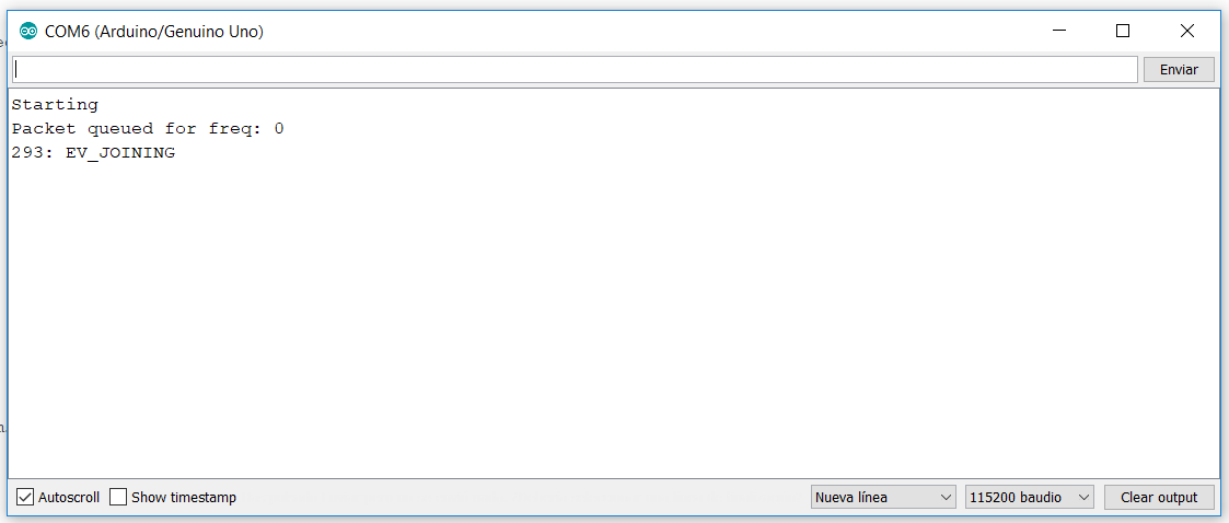
After that, I edited the NWKSKEY, APPSKEY and DEVADDR and I wrote my data provided by the Applications TTN’s page, after that I compiled the code with no problems and I checked the Monitor Serie and it looks like this:
image

The device status in TTN is “never seen”.

Then I tried other tutorial: https://github.com/thomaslaurenson/Dragino_LoRaShield_Node_AU915

I tought that this one was going to work, but no :sweat_smile:
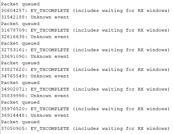
The Monitor Serie window looks like this and never changes:
image

I read this thread: Node: Need a sketch that works with Dragino LoRa Shield & Arduino Uno
and I see that people had similar problems.

Any suggestions?
I will be very grateful if someone helps me, thanks in advance and greetings from Honduras!

Updating: I’ve tried the TTN connection with my RAK 811 node and it is all OK, the node sends the payload as expected, also, my Rak 831 gateway with Raspberry Pi Zero W is working great, but I can´t make that the dragino shield with my arduino works, I don´t know what else I can do, Dragino support center is not giving me help as I expected :sweat_smile:

I need a little help friends, greetings!!!

Having similar issues with their rpi lorwan hat, been going around in circles for a few weeks.
I also need to us the us915.

Its about to get thrown into the trash can!

1 Like

The thing to realize with vendors like this is that they make hardware; they’re not good at software or support, so generally you buy from them if you already have a sense that you’ll be able to use the hardware without their assistance.

The LMiC code is more or less abandoned upstream, but exists in various unofficial branches. One of the ones getting more attention lately is https://github.com/mcci-catena/arduino-lmic

That said, using an Uno as the base system has never really been mainstream (in the case where the base system runs the LoRaWAN stack; it is more common with an AT-command set type module) - AFAIK it’s not a case getting any regular testing (nor one the maintainer is likely to have any interest in) so using that would require more effort on your own than using one of the supported ARM-based host boards with an Arduino port.

Similarly, using a pi as a host is a bit odd, there’s someone at Adafruit working on it for their hardware (you might learn from their efforts but please don’t ask them for support of something bought elsewhere). On the plus side I guess a pi would let you experiment and compile right on the node, but its less deterministic OS may require building in some extra padding in the receive window (turning the receiver on earlier, and setting it to seek preamble for more symbols) - something you could do since your pi itself is so power hungry the whole thing would need to be mains powered. But typically if you can put a pi somewhere you’d put a real network connection, LTE modem, or maybe one of its newer IoT-targeted variations on it, etc.

All of that said, there are only a little over a half dozen signals required to connect an SX127x to a host system, so it’s not like you have to throw hardware away - for a bench experiment, you can graft a LoRa add-on intended for one system onto another, as long as you get the connections right and avoid 5v host processors.

In terms of getting things working, some key suggestions

  • Initially start with ABP without ADR, so that the node can send irrespective if it never gets an answer from the network (ABP with ADR is historically broken in LMiC, it will get confused thinking it needs to send an OTAA join and end up in an endless loop)

  • Make the node print out when it actually transmits, all of the frequency, air settings like spreading factor, bandwidth, IQ inversion, etc. And a hexdump of the encrypted packet actually sent

  • Get your gateway somewhere quiet (or get a connectorized 50 ohm resistor to use as its “antenna”) where you are not regularly seeing packets from other sources, so that when you do see a RAW packet, you have a fair chance of believing it is from your node. Then you can use something like the online lora decoder to pull it apart and understand the fields, in case your traffic is not yet being actually accepted as valid by TTN. Even without using dummy keys you might be willing to put into that web page, you’ll notice there or in the LoRaWAN spec that you can read the node’s device address right out of the still encrypted packet, so you can readily tell what traffic is or isn’t yours.

1 Like

I worked out the problem today. The LMIC_PI-master code frequency list for rm915 are incorrect for Australia.

All the 915 frequencies listed in the code are all for South America I had to use a spectrum analyser to pick it up. Which helped me find the conflicting code and check against where it should be.

As a quick test I compiled the code using the CFG_eu868 and commented out the CFG_us915. I then left all the code in except swapped out all the eu868 frequencies from the lotabase.h and replaced them with the correct ones for Australia starting at 916.8mhz on the first channel and bingo.

Typically regions differ in more than just frequency range, so that’s probably not a good idea, at least beyond initially showing that the hardware is not completely broken. Things like the number of channels, data rates, fallback receive windows, etc may be different - and also there may be unique regulatory requirements that the non-frequency settings from another region would violate.

You might check if the other LMiC repo I linked above may have more accurate region definitions.

Note that there exists both an AU915 and an AS923 you may need to figure out which is relevant, the LoRaWAN docs list both as potentially applicable to Australia.

1 Like

Thanks for your concern the first 8 channels are masked out as they are owned by a cellular carrier.

The frequencies added are the ACMA free range to be used for Australia and are the correct frequencies to use here. They are also listed as the correct frequencies to use here on the things website.

You aren’t understanding the point being made - region settings are not just frequency plan, they also specify and DIFFER in things like uplink to downlink mapping, data rates, etc.

So copying a different region’s code and editing just the frequencies will likely not work - it may seem to at first, but you’ll run into a difference of behavior between nodes and server and suffer unexplained issues until you find that.

I do understand the point being made.

Now I know it ‘works’ after finding absolutely no working code or help for Australia for this device for the last 3 weeks I can finally work on getting it to work correctly and see what else needs to be changed. Unless you’re willing to do it? But I don’t think so.

At least any aussies that come across this will know why it doesn’t work and where to look.

1 Like

Hi @ccall48
Happy to see that you made it work, I will continue trying today, I will edit some of the code guiding me from what you mentioned before, thanks for your contribution friend!
If I get connected, I will say what I did.
Greetings.

@ccall48 sorry I didnt find this earlier - I have done several dragino shields - the latest was helping someone get one running just yesterday.

After a bit of hair pulling - it is as simple as using the MCCI library noted above by @cslorabox , changing the frequency to AU921 in the config file and including one line in your setup code to select sub band 2 (starting at 916.8)

Get the pin mapping correct and you’re good to go on AU915 TTN gateways

If I can help you out in any way let me know

cheers
Paul

1 Like

Hey @Paul_Stewart,

Do you think that’ll work with the RPi dragino sheild? I’ve trolled through some code the past few weeks and there is a lot that doesn’t work and a lot that I don’t comprehend not coming from a C background.

@sebasretes if your’re using the arduino dragino, Pauls answer should get you going! As you may not have a lora plan I advised above.

1 Like

Here is a sketch I use for OTAA, should work for you with the libraries I talked about above

/*******************************************************************************
 * Copyright (c) 2015 Thomas Telkamp and Matthijs Kooijman
 *
 * Permission is hereby granted, free of charge, to anyone
 * obtaining a copy of this document and accompanying files,
 * to do whatever they want with them without any restriction,
 * including, but not limited to, copying, modification and redistribution.
 * NO WARRANTY OF ANY KIND IS PROVIDED.
 *
 * This example sends a valid LoRaWAN packet with payload "Hello,
 * world!", using frequency and encryption settings matching those of
 * the The Things Network.
 *
 * This uses OTAA (Over-the-air activation), where where a DevEUI and
 * application key is configured, which are used in an over-the-air
 * activation procedure where a DevAddr and session keys are
 * assigned/generated for use with all further communication.
 *
 * Note: LoRaWAN per sub-band duty-cycle limitation is enforced (1% in
 * g1, 0.1% in g2), but not the TTN fair usage policy (which is probably
 * violated by this sketch when left running for longer)!
 * To use this sketch, first register your application and device with
 * the things network, to set or generate an AppEUI, DevEUI and AppKey.
 * Multiple devices can use the same AppEUI, but each device has its own
 * DevEUI and AppKey.
 *
 * Do not forget to define the radio type correctly in config.h.
 *
 *******************************************************************************/
#include <lmic.h>
#include <hal/hal.h>
#include <SPI.h>
// This EUI must be in little-endian format, so least-significant-byte
// first. When copying an EUI from ttnctl output, this means to reverse
// the bytes. For TTN issued EUIs the last bytes should be 0xD5, 0xB3,
// 0x70.
static const u1_t PROGMEM APPEUI[8]={ insert yours here };
void os_getArtEui (u1_t* buf) { memcpy_P(buf, APPEUI, 8);}
// This should also be in little endian format, see above.
static const u1_t PROGMEM DEVEUI[8]={ insert yours here };
void os_getDevEui (u1_t* buf) { memcpy_P(buf, DEVEUI, 8);}
// This key should be in big endian format (or, since it is not really a
// number but a block of memory, endianness does not really apply). In
// practice, a key taken from ttnctl can be copied as-is.
// The key shown here is the semtech default key.
static const u1_t PROGMEM APPKEY[16] = { insert yours here };
void os_getDevKey (u1_t* buf) {  memcpy_P(buf, APPKEY, 16);}
static uint8_t mydata[] = "Hello,hello!";
static osjob_t sendjob;
// Schedule TX every this many seconds (might become longer due to duty
// cycle limitations).
const unsigned TX_INTERVAL = 15;
// Pin mapping
// TL Modifications:
// Specifically for Arduino Uno + Dragino LoRa Shield US900
const lmic_pinmap lmic_pins = {
    .nss = 10,
    .rxtx = LMIC_UNUSED_PIN,
    .rst = 9,
    .dio = {2, 6, 7},
};
void onEvent (ev_t ev) {
    Serial.print(os_getTime());
    Serial.print(": ");
    switch(ev) {
        case EV_SCAN_TIMEOUT:
            Serial.println(F("EV_SCAN_TIMEOUT"));
            break;
        case EV_BEACON_FOUND:
            Serial.println(F("EV_BEACON_FOUND"));
            break;
        case EV_BEACON_MISSED:
            Serial.println(F("EV_BEACON_MISSED"));
            break;
        case EV_BEACON_TRACKED:
            Serial.println(F("EV_BEACON_TRACKED"));
            break;
        case EV_JOINING:
            Serial.println(F("EV_JOINING"));
            break;
        case EV_JOINED:
            Serial.println(F("EV_JOINED"));
            {
              u4_t netid = 0;
              devaddr_t devaddr = 0;
              u1_t nwkKey[16];
              u1_t artKey[16];
              LMIC_getSessionKeys(&netid, &devaddr, nwkKey, artKey);
              Serial.print("netid: ");
              Serial.println(netid, DEC);
              Serial.print("devaddr: ");
              Serial.println(devaddr, HEX);
              Serial.print("artKey: ");
              for (int i=0; i<sizeof(artKey); ++i) {
                Serial.print(artKey[i], HEX);
              }
              Serial.println("");
              Serial.print("nwkKey: ");
              for (int i=0; i<sizeof(nwkKey); ++i) {
                Serial.print(nwkKey[i], HEX);
              }
              Serial.println("");
              LMIC_setSeqnoUp(140);
            }
            // Disable link check validation (automatically enabled
            // during join, but not supported by TTN at this time).
            LMIC_setLinkCheckMode(0);
            break;
        case EV_RFU1:
            Serial.println(F("EV_RFU1"));
            break;
        case EV_JOIN_FAILED:
            Serial.println(F("EV_JOIN_FAILED"));
            break;
        case EV_REJOIN_FAILED:
            Serial.println(F("EV_REJOIN_FAILED"));
            break;
            break;
        case EV_TXCOMPLETE:
            Serial.println(F("EV_TXCOMPLETE (includes waiting for RX windows)"));
            if (LMIC.txrxFlags & TXRX_ACK)
              Serial.println(F("Received ack"));
            if (LMIC.dataLen) {
              Serial.println(F("Received "));
              Serial.println(LMIC.dataLen);
              Serial.println(F(" bytes of payload"));
            }
            // Schedule next transmission
            os_setTimedCallback(&sendjob, os_getTime()+sec2osticks(TX_INTERVAL), do_send);
            break;
        case EV_LOST_TSYNC:
            Serial.println(F("EV_LOST_TSYNC"));
            break;
        case EV_RESET:
            Serial.println(F("EV_RESET"));
            break;
        case EV_RXCOMPLETE:
            // data received in ping slot
            Serial.println(F("EV_RXCOMPLETE"));
            break;
        case EV_LINK_DEAD:
            Serial.println(F("EV_LINK_DEAD"));
            break;
        case EV_LINK_ALIVE:
            Serial.println(F("EV_LINK_ALIVE"));
            break;
         default:
            Serial.println(F("Unknown event"));
            break;
    }
}
void do_send(osjob_t* j){
    // Check if there is not a current TX/RX job running
    if (LMIC.opmode & OP_TXRXPEND) {
        Serial.println(F("OP_TXRXPEND, not sending"));
    } else {
        // Prepare upstream data transmission at the next possible time.
        LMIC_setTxData2(1, mydata, sizeof(mydata)-1, 0);
        Serial.println(F("Packet queued"));
    }
    // Next TX is scheduled after TX_COMPLETE event.
}
void setup() {
    Serial.begin(9600);
    Serial.println(F("Starting"));
    #ifdef VCC_ENABLE
    // For Pinoccio Scout boards
    pinMode(VCC_ENABLE, OUTPUT);
    digitalWrite(VCC_ENABLE, HIGH);
    delay(1000);
    #endif
    // LMIC init
    os_init();
    // Reset the MAC state. Session and pending data transfers will be discarded.
    LMIC_reset();
         
    // Let LMIC compensate for +/- 1% clock error
    LMIC_setClockError(MAX_CLOCK_ERROR * 1 / 100);
    LMIC_selectSubBand(1);
    // Start job (sending automatically starts OTAA too)
    do_send(&sendjob);
}
void loop() {
    os_runloop_once();
}
1 Like

sorry haven’t got any experience with the Rpi shield, just arduino.

Maybe the library will still give you some hints about the frequency plan - bit beyond my capabilities sorry

cheers
Paul

1 Like

Understand this. Was an attempt at proving the hardware works only after 3 weeks of on and off attempts with no avail. Also there is no information anywhere for the pihat to be used as a node that I’ve come across (that will work in Australia without operating on banned frequencies).

1 Like

I do understand, otherwise this topic would have been killed ages ago.

That is actually not too surprising. Nodes are generally low power (consuming) devices which an RPi isn’t. So most, if not all development, is geared towards other hardware. For the LMIC stack mainly Arduino variants and ESP devices.

Hi @Paul_Stewart, I appreciate and I am very grateful that you have shared your code.

I used this library: https://github.com/mcci-catena/arduino-lmic
Then I edited the lmic_project_config.h and used #define CFG_au921 1
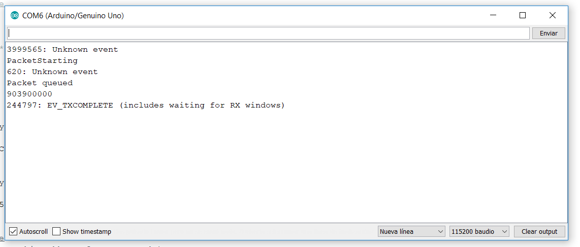
After that, I used your sketch and I wrote my ttn otaa device data, but I can’t make it work, there is no payload seen in ttn console and my monitor serie looks like this:
image
Thanks for your help.

That is really weird that it is getting a TX Complete because it means that it has joined without issue.

Maybe a stupid question, but are you looking at the correct application.

Might be a TTN issue at the moment, there seems to be a few issues.

Did you make sure your Dev EUI and App Eui is in LSB format and App Key is in MSB format

Cheers
Paul

Actually, no, that just means a packet has been sent - which could well be the join request itself. It does not mean anything has been received by the gateway, nor any downlink received in return.

Generally it’s best to make the node log the frequency and associated settings when it transmits and make sure those match what the gateway is listening for. This is a little more tricky in Arduino context, as the logging would need to come from within LMiC C code but the usual means of generating output are C++ classes; there may be an existing logging function or you can create you own.

Also if you own the gateway in question and can put it somewhere quiet, check for raw transmissions that might be related to the node being tested.

I thought the TX Complete could only happen after a successful OTAA join process.

If joining fails it will never get to sending the data packet

To get a better idea of what’s going on you can set the debugging level higher in LMIC to show what frequencies are being used