(repost of https://forum.loraserver.io/t/schematic-kerlink-wirgrid-debug-board/3837/2)
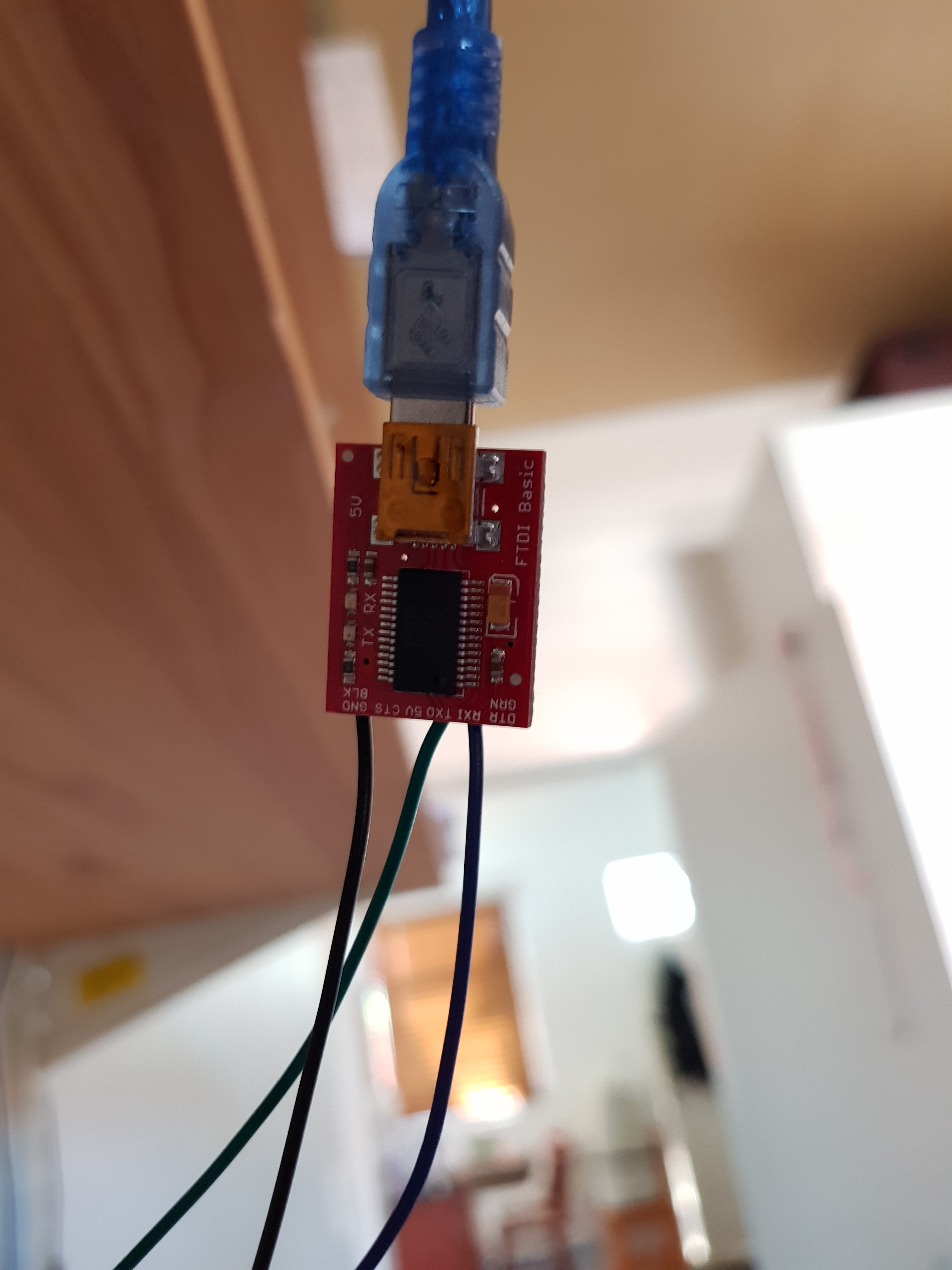
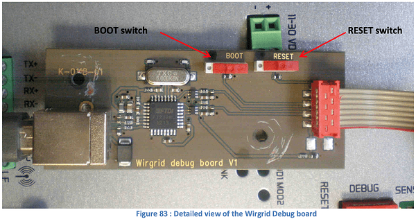
If you happen to mess up the network or firewall config on your Kerlink gateway, the only way to get back into it is using a Wirgrid Debug probe. These things are really expensive and/or difficult to get your hands on. Looking at the photos of this debug probe one will see that it uses an FTDI FT232BL. This is a USB to serial chip which is very often used in USB to Serial/UART modules. This confirms that there must be a serial interface on the Kerlink’s debug port. From experimentation I got a working terminal via the debug port using a Sparkfun FTDI basic breakout for 3.3V: https://www.sparkfun.com/products/9873
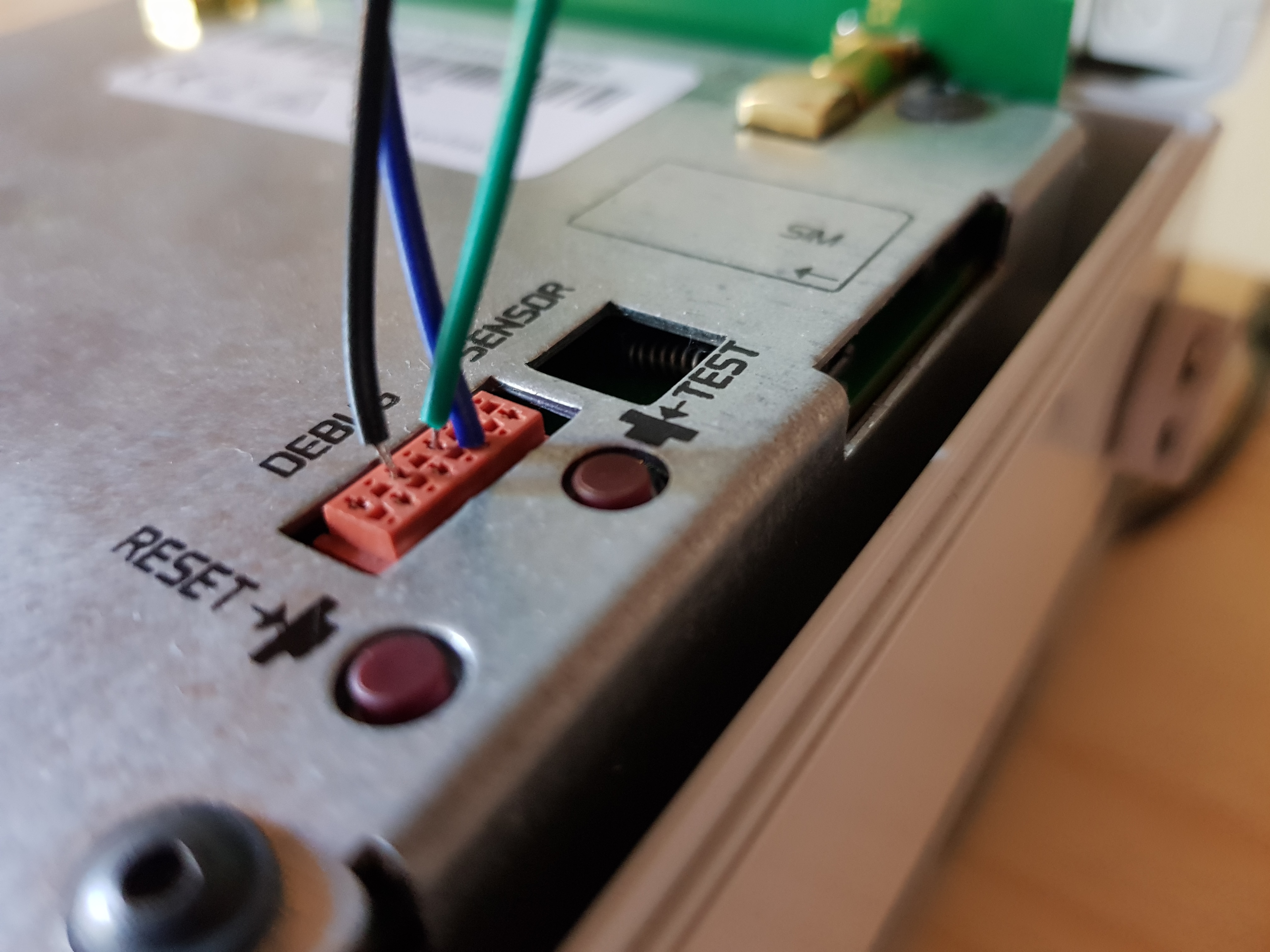
The pinouts of the debug header on the Kerlink itself I used are as follows:
# 1
2 #     O TEST
# 3
4 #
# 5
6 #
# 7
8 #
        O RESET
- Vcc?? - unsure about this
- Looks like Reset
- TX (connect to dongle RX) - reads as 3.3V on a multimeter, indicating 3.3V TTL logic - so use a 3.3V FTDI breakout.
- RX (connect to dongle TX)
- Looks like Boot
- Ground (connect to dongle ground)
- ??
- ??


