Conflict with Dragino Uno shield and Nova SDS011 dust sensor

Using an Arduino Uno with a Dragino Uno LoRa shield I discover serious problems sending data coming from a Nova SDS011 dust sensor to TTN. The pins D3, D4 and D5 are not used by the shield (see attachment) so I use pins D3 and D4 for Tx and Rx of the dust sensor. The sensor values are displayed in the serial monitor as long as I disable the os_init and LMIC_reset lines (line 62 and 63 marked ***) in the sketch. I have to disable them both, disabling only one of them makes no difference. Enabling these lines stops the complete (all!) output to the serial monitor and then there is also no data sent to my TTN gateway.

I have tested the TTN part, without using the SDS011 part, and this part looks okay so the code for TTN is not the problem. It turned out there is a conflict between the SDS011 and the LMIC library. Can someone be so kind to look what went wrong?

#include “SdsDustSensor.h”
#include <lmic.h>
#include <hal/hal.h>
#include <SPI.h>

SdsDustSensor sds(3, 4); // SDS011 Tx Rx

int minutesDelay = 1;
int pm10;
int pm25;

static const PROGMEM u1_t NWKSKEY[16] = { 0xXX, 0xXX, 0xXX, 0xXX, 0xXX, 0xXX, 0xXX, 0xXX, 0xXX, 0xXX, 0xXX, 0xXX, 0xXX, 0xXX, 0xXX, 0xXX }; // TTN Network session key
static const u1_t PROGMEM APPSKEY[16] = { 0xXX, 0xXX, 0xXX, 0xXX, 0xXX, 0xXX, 0xXX, 0xXX, 0xXX, 0xXX, 0xXX, 0xXX, 0xXX, 0xXX, 0xXX, 0xXX }; // TTN Application session key
static const u4_t DEVADDR = 0xXXXXXXXX; // TTN End-device address

void os_getArtEui (u1_t* buf) { }
void os_getDevEui (u1_t* buf) { }
void os_getDevKey (u1_t* buf) { }

static osjob_t sendjob;

// Pinmapping Dragino Uno Shield
const lmic_pinmap lmic_pins = {
.nss = 10,
.rxtx = LMIC_UNUSED_PIN,
.rst = 9,
.dio = {2, 6, 7},
};

void onEvent (ev_t ev) {
switch(ev) {
case EV_TXCOMPLETE:
break;
}
}

void do_send(osjob_t* j){
static uint8_t message[4];
message[0] = highByte(pm10);
message[1] = lowByte(pm10);
message[2] = highByte(pm25);
message[3] = lowByte(pm25);
if (LMIC.opmode & OP_TXRXPEND) {
Serial.println(“Nothing sent (OP_TXRXPEND)”);
} else {
LMIC_setTxData2(1, message, sizeof(message), 0);
Serial.print(“Sent: (”);
Serial.print(pm10);
Serial.print("/");
Serial.print(pm25);
Serial.println(")");
}
}

void setup() {
Serial.begin(9600);
Serial.println(“Dust sensor”);
sds.begin();
Serial.println(sds.queryFirmwareVersion().toString()); // prints firmware version
Serial.println(sds.setActiveReportingMode().toString()); // ensures sensor is in ‘active’ reporting mode
Serial.println(sds.setCustomWorkingPeriod(minutesDelay).toString()); // sensor sends data every x minutes
// os_init(); // ***** Error when unmarked *****
// LMIC_reset(); // ***** Error when unmarked *****
uint8_t appskey[sizeof(APPSKEY)];
uint8_t nwkskey[sizeof(NWKSKEY)];
memcpy_P(appskey, APPSKEY, sizeof(APPSKEY));
memcpy_P(nwkskey, NWKSKEY, sizeof(NWKSKEY));
}

void loop() {
PmResult pm = sds.readPm();
if (pm.isOk()) {
Serial.print("PM2.5 = “);
Serial.print(pm.pm25);
Serial.print(”, PM10 = ");
Serial.println(pm.pm10);
} else {
// Do nothing
}
delay(5000);
}
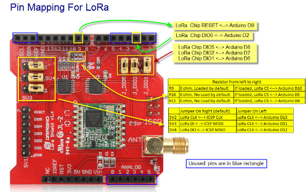
Shield

1 Like

You’re going to need to better integrate the task of reading the sensors with those schedules by LMiC to run the radio. Try to find an example that actually reports a sensor reading, and replace its sensor code with yours. Beware of using Delay() type paradigms, as nothing else can happen during that.

Thanks for your advice. I’ve viewed sketches with temperature/humidity sensors but they differ, sometimes completely, from mine. As a beginner- and due to my lack of LMiC knowledge - I really don’t know how to convert them to my configuration. Maybe you can be a bit more specific?

And, before testing and trying with the LMiC- and SDS-library I use in the sketch, do you think I can exclude conflicts between those libraries?

You conflict does not appear to be between “libraries” but rather that you have not created a program flow which accomplishes both goals.

This is where you can learn from programs which integrate LMiC with even entirely different sensors.

Sorry but you are wrong.

Due to my lack of programming skills I have exclude conflicts by minimizing the sketch but the issue persists. As soon as I mark (//) the line:

Serial.println(sds.setCustomWorkingPeriod(minutesDelay).toString());

the output (only from the loop) is shown in the serial monitor. When this line is unmarked I need to mark BOTH lines below to see the output from the loop, the sensor firmware, the mode and the working period in the serial monitor:

os_init(); 
LMIC_reset();

Would be great if someone could help me to handle this! The minimized sketch:

#include “SdsDustSensor.h”
#include <lmic.h>
#include <hal/hal.h>
#include <SPI.h>

SdsDustSensor sds(3, 4); // SDS011 Tx Rx
int minutesDelay = 1;

static const PROGMEM u1_t NWKSKEY[16] = { xxx }; // TTN Network session key
static const u1_t PROGMEM APPSKEY[16] = { xxx }; // TTN Application session key
static const u4_t DEVADDR = xxx; // TTN End-device address

void os_getArtEui (u1_t* buf) { }
void os_getDevEui (u1_t* buf) { }
void os_getDevKey (u1_t* buf) { }

static osjob_t sendjob;

// Pinmapping Dragino Uno Shield
const lmic_pinmap lmic_pins = {
.nss = 10,
.rxtx = LMIC_UNUSED_PIN,
.rst = 9,
.dio = {2, 6, 7},
};

void onEvent (ev_t ev) {
switch(ev) {
case EV_TXCOMPLETE:
break;
}
}

void do_send(osjob_t* j){
if (LMIC.opmode & OP_TXRXPEND) {
Serial.println(“Nothing sent (OP_TXRXPEND)”);
} else {
// do nothing
}
}

void setup() {
Serial.begin(9600);
sds.begin();
Serial.println(sds.queryFirmwareVersion().toString()); // prints firmware version
Serial.println(sds.setActiveReportingMode().toString()); // ensures sensor is in ‘active’ reporting mode
Serial.println(sds.setCustomWorkingPeriod(minutesDelay).toString()); // sensor sends data every x minutes
os_init();
LMIC_reset();
uint8_t appskey[sizeof(APPSKEY)];
uint8_t nwkskey[sizeof(NWKSKEY)];
memcpy_P(appskey, APPSKEY, sizeof(APPSKEY));
memcpy_P(nwkskey, NWKSKEY, sizeof(NWKSKEY));
}

void loop() {
Serial.println(“Serial Monitor Output”);
}

Again, this is because you have not established a single program flow with accomplishes all of the needs. LMiC itself has something of a scheduler, you will need to cooperate with that.

If you take time to actually understand how your sensors work, you’ll see how to substitute them in place of different sensors in a sound example program.

Conversely if you just keep blindly calling methods with no idea what they do, you are unlikely to get anywhere.

Dear Hans,

I had similar issues with LMIC and sensors and some erratic beahaviour. I think it’s a memory issue. It seems to me that the Arduino is running into trouble if you use multiple C-Libraries with lots of classes and pointers. For me, moving to a more simple library (SDS011_vers) helped. In the end, I managed to connect the SDS011 and two I2C sensors and send out the LoRa packets via LMIC and RFM95 chip. I will post the code on GitHub later.

1 Like

Hi Niels,

Using this library with the Dragino board and the sensor was frustrating so I now use a The Things Uno board with TTN library and this works great. I now use it 8+ weeks without any problem.

Regards, Hans.

Dear niels80 ,
Did you post the code yet
i have the same problem , i used dragino and arduino uno and after sending the (hello world )data and recieving it by ttn
i struggle with the sensed data cause the sensed data need to mesured at loop function.
and the (os_runloop_once() already there to loop the limic library ) so its difficult to integrate a variable to the my data array which defined …
so i need to add the sence data to payload before sending it (or run (os_runloop_once()).
im new in arduino code thanks for ur patient.