how do I send messages using this board only on one SF and one Frequency?
Hi,
I guess you use a single channel gateway 
This answer is not specific to LoRa32u4 board.
To force Spread Factor, look around LMIC_setDrTxpow() examples.
To force channel selection, define and disable channel using LMIC_setupChannel() and LMIC_disableChannel().
Good luck.
Hey omuron, did you make any progress on this? I’m seeing values >5 but floating with the same standard code - maybe the v1.3 boards have the voltage divider disconnected (or mosfet driven, as surmised above, but I didn’t spot a new mosfet?).
There is still that bridge pad on the underneath that’s unexplained.
Thanks,
Bruce
Still no official datasheet ![]()
I guess you have to find how to activate this battery mosfet by yourself (or ask BSFrance support).
Good luck!
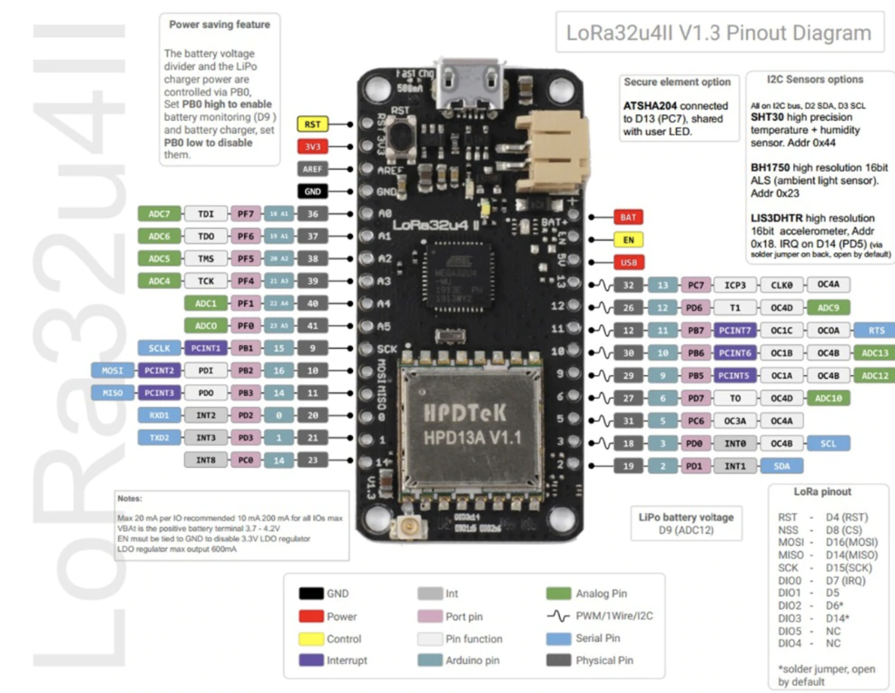
As far as the mosfet goes, I did try bringing PB0 high (and low…just for fun) and this didn’t change the readings. PB0 on the 32u4 is SS/D17 right? I saw no change at least while it was on USB when I defined it as an output and took it low or high, then read A9. Even with a delay.
If there is a mostfet then it appears to be on in any case, I’m using v1.3 of the BSFrance Lora32u4 board, and the following code seems to work. I’m concluding it’s basically pre-scaled to between 0-1023 for the full battery voltage already…which is a bit special. I saw the voltage go up all day and top out at ~1023, measured the BAT pin at 4.2v
#define VBATPIN A9
    float measuredvbat = analogRead(VBATPIN);
    measuredvbat *= 4.2;  // Multiply by 4.2V, our max batt voltage
    measuredvbat /= 1024; // convert to voltage
    Serial.print("VBat: " ); Serial.println(measuredvbat);
The battery charger led turns off at 4.2v too – I’m unclear how to turn it off otherwise, although I’d like to.
Finally spec for v 1.3

(Click right mouse button and select ‘Open image in new tab’ to view full image size.)
Right side is missing, can you share source file?
Tip, If pic is too big to show on forum you can right click and ‘view image’ in e.g. firefox - or copy/paste to image programme (Paint works!) - then shows full picture/higher res image 
So it’s definitively PB0 from the new docs - thanks! I will have another go this time using the registers instead of the Arduino mapped pins.
right click - View image
That was so obvious that I missed that one ![]() Thanks
Thanks
Does anyone know about ATSHA204 and I2C option?
No direct knowledge, but I’m assuming the I2C pins are connected to that pad on the back and you can fill that space with one of those chips? Also D14 optionally connected, which explains the chevron pad on the back.
In other news, here’s some charger (and voltage measuring) code - tested working! The orange LED turns on and off on command.
void charger(bool on) {
  DDRB |= (1<<PB0); // set PBO as output

  if(on) {
    PORTB |= (1<<PB0);
  } else {
    PORTB &= ~(1<<PB0);
  }
}
Anyone solved problem with small flash memory size ? I am trying to add QLED display driven by GitHub - olikraus/u8g2: U8glib library for monochrome displays, version 2, anyway complete code (Lora + display) is too big. IDE returns
Sketch uses 32044 bytes (111%) of program storage space. Maximum is 28672 bytes.
Spec shows 32K of flash, 2K of RAM (BSFrance LoRa32u4 II Lora Development Board v 1.3)
You can disable part of LMIC to save memory: Big LoRa32u4 boards topic . And then reduce prints as much as possible, and avoid to use the String object.
You’ve turned off DEBUG for the Lora code, and PING and BEACON?
e.g.
#define DISABLE_PING
#define DISABLE_BEACONS
in your lmic_project_config.h and maybe #undef DEBUG
That’s the worst drawback of this board.
If shrinking LMIC library is not enough, I see no easy answer. I guess you can find an alternative (and lighter) library for your LCD.
Tip for PlatformIO:
When using PlatformIO, project scoped settings can be specified in platformio.ini (preferred) instead of in lmic_project_config.h. The Arduino IDE unfortunately does not provide such option.
lmic_project_config.h defines project scoped settings at library sourcecode level instead of project level. Changing settings in lmic_project_config.h requires modification of library sourcecode which is maintenance intensive, error prone and difficult to automate and will be overwritten by library updates. Using platformio.ini for these settings instead is therefore preferred.
Functional equivalents for #define DISABLE_PING and #define DISABLE_BEACONS are shown in below platformio.ini example.
Note: Undefining DEBUG is possible with ‘-U DEBUG’ but this will only have effect if DEBUG was defined on the command line. It will not overrule any ‘#define DEBUG’ in sourcecode.
; File: platformio.ini

[env:lora32u4II]
platform = atmelavr
board = lora32u4II
framework = arduino

monitor_speed = 115200

lib_deps =
    MCCI LoRaWAN LMIC library

build_flags =
	; LMIC build options:
	-D DISABLE_PING
	-D DISABLE_BEACONS
    ; -D LMIC_DEBUG_LEVEL=2
    ; -D LMIC_PRINTF_TO=Serial
	; MCCI LoRaWAN LMIC library specific build options:
    ; Set suppress flag to suppress lmic_project_config.h
	; to allow project related settings to be defined here instead.
    -D ARDUINO_LMIC_PROJECT_CONFIG_H_SUPPRESS
    ; -D CFG_in866=1
    -D CFG_eu868=1
    ; -D CFG_us915=1
    ; -D CFG_au921=1
    ; -D CFG_as923=1
    ; -D CFG_as923jp=1
    -D CFG_sx1276_radio=1
    ; -D LMIC_USE_INTERRUPTS
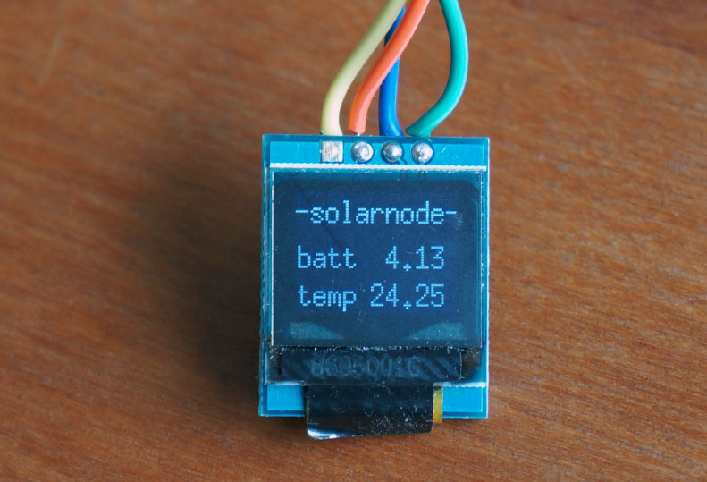
depends which oled… if its small and based on SSD1306 … yes, it worked for me

White 4Pin 0.66" OLED Display Screen IIC I2C SSD1306 64x48 for Adurino AVR STM32
see GitHub - greiman/SSD1306Ascii: Text only Arduino Library for SSD1306 OLED displays