Adafruit Feather 32u4 LoRa and BSFrance LoRa32u4 II boards
LoRa32u4 will be used as a general abbreviation for above family of boards.
The LoRa32u4 boards are a combination of an Atmel ATmega32u4 AVR MCU with a LoRa module and have Li-Ion/LiPo battery support (including charging). The Feather 32u4 LoRa is designed by Adafruit. The LoRa32u4 II board is designed by BSFrance and produced by DIYMall (which is actually a copy of the Adafruit Feather 32u4 LoRa).
The ATmega32u4 has built-in support for USB and does not require a separate USB to serial converter chip. This has advantages but also disadvantages: After a reset the serial port will be temporarily disconnected and switched to programming mode and automatically switches back after some seconds. This sometimes can give issues when uploading and/or when using the Serial Monitor.
These boards have a separate LoRa antenna that connects via a tiny cable to the on-board IPEX/U.FL connector (for versions 1.1 and higher, version 1.0 only supported a wire antenna directly soldered to the board). The battery connector is a 2-pin JST-PH connector. The battery voltage can be monitored via an analog pin.
Hardware
Currently 5 different versions of the BSFrance LoRa32u4 II board exist.
Below is a brief description of each version:
-
Version 1.0
Uses an unshielded SX127x LoRa module.
Lacks a version number on the PCB.
Has a hole for soldering a simple wire antenna. No IPEX/U.FL antenna connector.
LoRa DIO0 is permanently wired to digital pin 7.
LoRa DIO1 has it own board pin but is not connected to any digital pin.
DIO1 pin must be manually wired to a digital pin (required for LoRa).
There are soldering pads/holes for DIO2 and DIO3 for manual wiring if needed. -
Version 1.1a
Like version 1.0 but in addition has an IPEX/U.FL LoRa antenna connector.
This model hash a version number on the top of the PCB: V1.1. -
Version 1.1b
Identical to version 1.1a but uses a shielded HPDTek LoRa module. -
Version 1.2
Like version 1.1b but the DIO1 board pin has been replaced by digital pin 14 (new).
DIO1, DIO2 and DIO3 now each have solder padson the PCB so they can be easily connected to a digital pin. Using the solder pads DIO1 can be connected to digital pin 1, DIO2 to digital pin 2 and DIO3 to digital pin 3.
Having the solder pads is great, but unfortunately they use digital pins 1, 2 and 3 for DIO which is a poor design choice because these pins serve other important functions:
Pin 1: Serial TX + Interrupt #3, Pin 2: I2C SDA + Interrupt #1, Pin 3: I2C SCL + Interrupt #0.
This model has version numbers on both sides of the PCB: V1.2. -
Version 1.3
For information about version 1.3 see post Settings for BSFrance LoRa32u4 II v1.3 further below.
Software
In addition to the hardware, software is needed for implementing the LoRaWAN protocol. The SX127x LoRa tranceiver provides LoRa radio modulation but it does not implement the LoRaWAN protocol. The protocol has to be implemented in software that needs to run on the ATmega32u4 MCU.
The following libraries implement a LoRaWAN protocol stack that can be used with the these boards:
-
LMIC-Arduino aka Classic LMIC is the original Arduino LMIC library but it is no longer maintained and has been deprecated. This library lacks the LoRaWAN compliancy needed for TTN/TTS V3.
-
MCCI LoRaWAN LMIC library aka MCCI LMIC is based on LMIC-Arduino and has been further developed. It contains several improvements, supports more regions and is actively maintained.
This library is now preferred but it uses more memory. For TTN/TTS V3 use of MCCI LMIC is required because its predecessor Classic LMIC lacks required LoRaWAN compliancy.
Each of these libraries has its own way of configuring (e.g. region/frequency) settings. For details check the readme and other documentation included with each library.
Both libraries contain examples for implementing a node for both ABP and OTAA activation.
Try to get the ttn-abp.ino example working first. If that works continue with the ttn-otaa.ino example. When both these examples work then the LoRaWAN part of your setup works. From there you can start to try more advanced sketches and adding features (e.g. sensors). ABP and OTAA require different keys and settings. See TTN Console and remarks in the sketches for more information.
Try to get the basics working first before asking questions about issues with other sketches.
For more information about available LoRaWAN libraries see:
Overview of LoRaWAN Libraries [HowTo]
LMIC Timing
When using the two common Arduino LMIC libraries on 8-bit ATmega328 and ATmega32U4 MCU’s (especially 8 MHz like on LoRa32U4) it is required to relaxed LMIC timing, otherwise down link messages and OTAA joins on lower spreading factors will likely fail.
LMIC timing can be relaxed with LMIC_setClockError() as shown below where it is
added to the ttn-otaa.ino example.
A value of 3 percent is usually sufficient for LoRa32u4. Different LMIC libraries may need a different value. The 3 percent was empirically determined. During testing of joins and downlink messages my observation was that the classic LMIC-Arduino library needs a little higher value than the MCCI LoRaWAN LMIC library.
    // LMIC init
    os_init();
    // Reset the MAC state. Session and pending data transfers will be discarded.
    LMIC_reset();

    // ### Relax LMIC timing ###
    // Required for ATmega328/ATmega32U4 (8MHz) otherwise downlink messages
    // and OTAA joins on lower spreading factors will likely fail.
    #define LMIC_CLOCK_ERROR_PERCENTAGE 3
    LMIC_setClockError(LMIC_CLOCK_ERROR_PERCENTAGE * (MAX_CLOCK_ERROR / 100.0));

    // Start job (sending automatically starts OTAA too)
    do_send(&sendjob);
Wiring
For LoRa modulation the LMIC libraries only need DIO0 and DIO1 to be wired.
For FSK modulation (which is normally not used) DIO0 and DIO2 need to be wired.
Adafruit Feather 32u4 LoRa and BSFrance LoRa32u4 II versions 1.0 and 1.1
DIO0: Is already hard-wired on the PCB to pin 7.
DIO1: Must be manually wired. It is preferred to wire DIO1 to digital pin 5.
Several examples on the web suggest to wire DIO1 to pin 6. Probably because it is next to pin 7 which is already hard-wired to DIO0. But wiring DIO1 to pin 5 instead has the following advantages:
- It leaves pin 6 available which also provides ADC functionality (which pin 5 does not).
- On the BSFrance version 1.3, DIO1 is already wired to pin 5 by default. Using consistent wiring for all versions of the board allows that software can run on all versions of the board without having to reconfigure pin mappings.
- For the Adafruit Feather 32u4 if you want you can still use pin 6 if you prefer. Adafruit tries to keep pin numbers identical on different Feather boards. You will have to change your pin mapping in the software accordingly however.
- Uses 2.54mm less wire.

BSFrance LoRa32u4 II version 1.2
DIO0: Is already hard-wired on the PCB to pin 7.
DIO1: Must be manually connected via solder bridge on the PCB or manually wired.
The solder bridge on version 1.2 connects DIO1 to pin 1 which is part of the serial interface. If you plan to use the serial interface (e.g. to connect a GPS module) then connecting DIO1 to pin 1 via the solder bridge is not a good idea. In that case it should be manually wired to pin 5.
Manual wiring will require some solder skills because the wire must be soldered directly to the DIO1 pad of the LoRa module. Version 1.2 does not have a board pin for DIO1 that the older boards had.
BSFrance LoRa32u4 II versions 1.3.
DIO0: Is already hard-wired on the PCB to pin 7.
DIO1: Is already connected to pin 5 via solder bridge on the PCB.
LMIC Pin Mapping
For:
- LoRa32u4 II versions 1.0, 1.1 and 1.2 where DIO1 is manually wired to pin 5.
- Lora32u4 II version 1.3 where DIO1 is default connected to pin 5 via solder bridge on PCB.
If you have manually wired DIO1 to a different pin than pin 5 then replace 5 below with the corresponding pin number.
const lmic_pinmap lmic_pins = {
  .nss = 8,
  .rxtx = LMIC_UNUSED_PIN,
  .rst = 4,
  .dio = {/*dio0*/ 7, /*dio1*/ 5, /*dio2*/ LMIC_UNUSED_PIN}
};
For LoRa32u4 II v1.2 where DIO1 is manually connected to pin 1 via the solder bridge on the PCB.
const lmic_pinmap lmic_pins = {
  .nss = 8,
  .rxtx = LMIC_UNUSED_PIN,
  .rst = 4,
  .dio = {/*dio0*/ 7, /*dio1*/ 1, /*dio2*/ LMIC_UNUSED_PIN}
};
Useful links
- Overview of LoRaWAN Libraries [HowTo].
- Pinout diagrams for above and other boards can be found in the following pinout-diagrams repository.
Pictures
Version 1.0
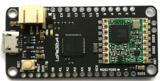
BSFrance LoRa32u4 II version 1.0 - Top
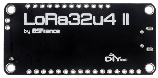
BSFrance LoRa32u4 II version 1.0 - Bottom
Version 1.1
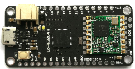
BSFrance LoRa32u4 II version 1.1a - Top
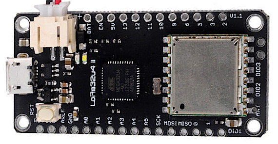
BSFrance LoRa32u4 II version 1.1b - Top
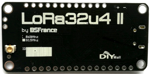
BSFrance LoRa32u4 II version 1.1 - Bottom
Version 1.2
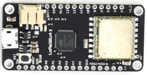
BSFrance LoRa32u4 II version 1.2 - Top
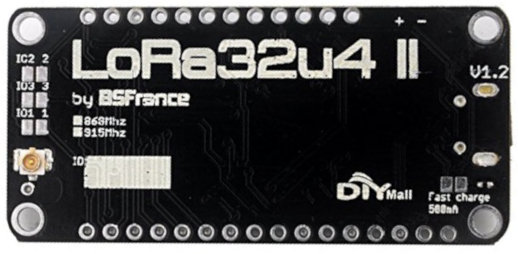
BSFrance LoRa32u4 II version 1.2 Bottom
