Settings for BSFrance LoRa32u4 II v1.3
Click here to go back to the topic start
BSFrance has not yet updated their documentation and Arduino core since LoRa32u4 II v1.1.
Like previously for version v1.2 we will have to do our own research for v1.3 again.
I don’t have the board but from @fanysoft’s pictures of the LoRa32u4 II v1.3 board I was able to make the following observations and conclusions:
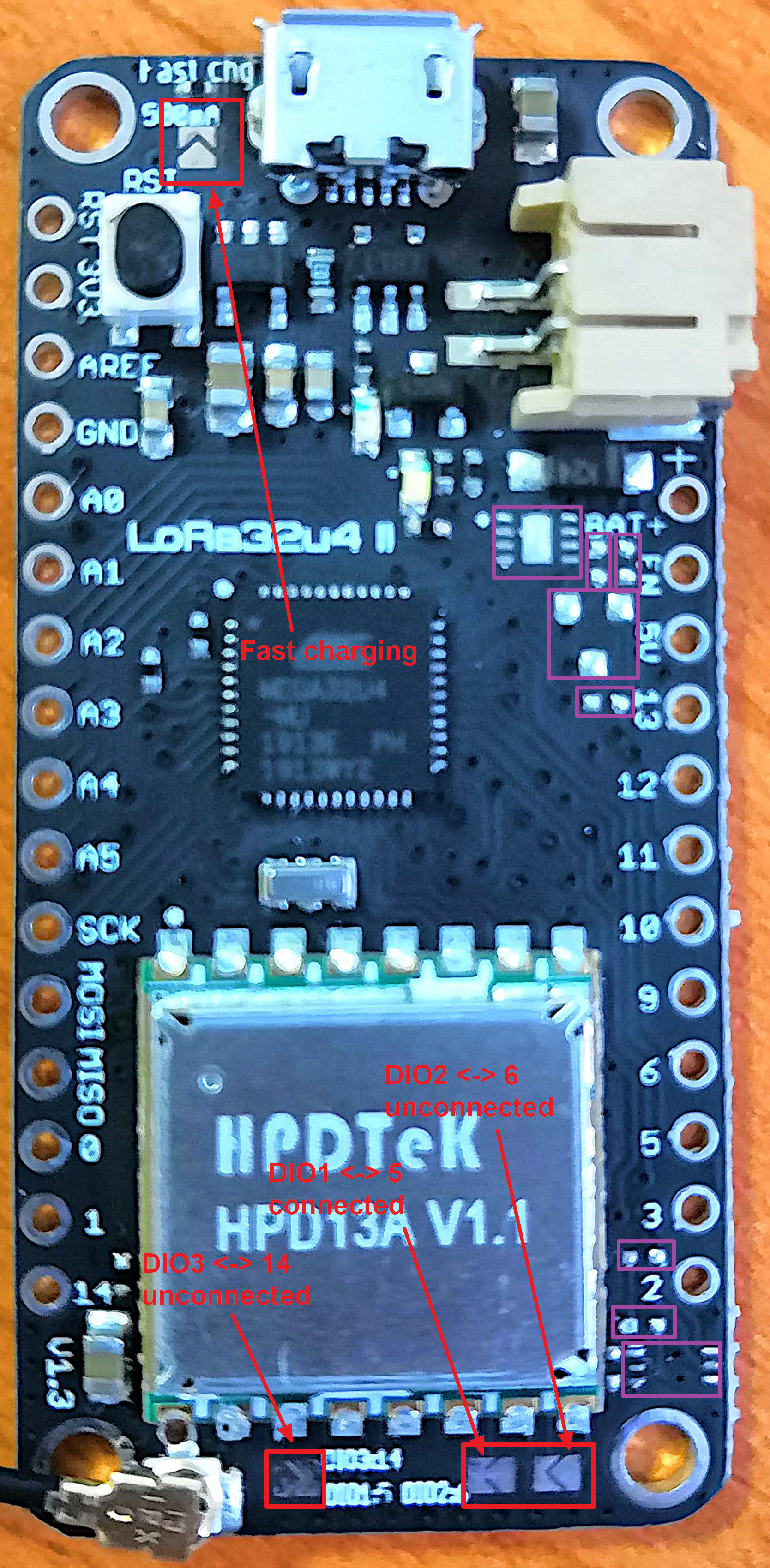
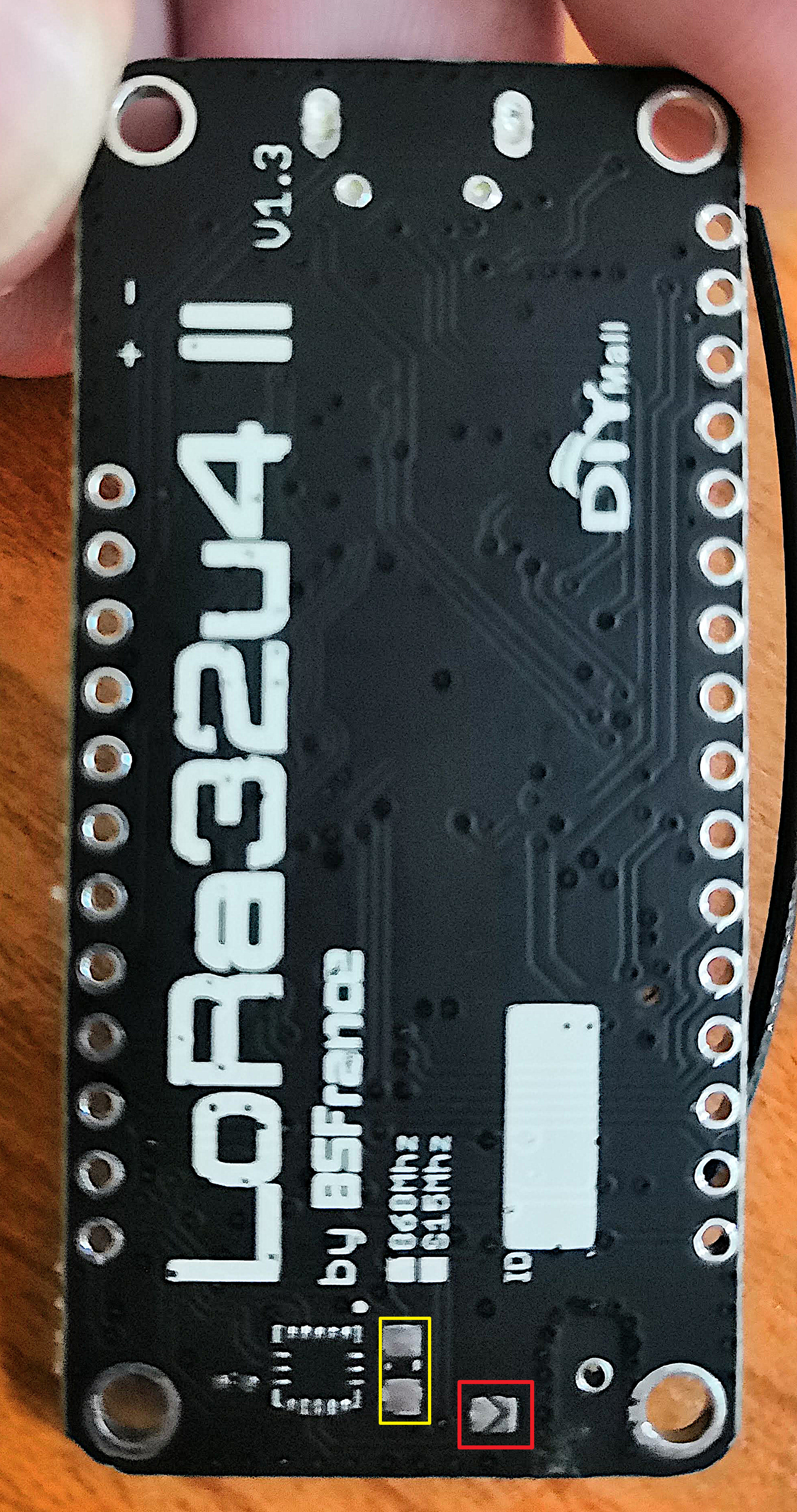
- There are 5 solder jumpers, one is default connected (closed) and the other four are not (open), four are labled and the one on the bottom side is not:
- DIO1 (default connected)
- DIO2
- DIO3
- Fast charging (will use a higher charge current for the Li-ion/LiPo battery)
- One on the bottom side, not labled (unclear what this is for) - There are several places on the board where components are not installed. This could be intended for adding additional (optional) components later, or may indicate a design change for which the PCB was not updated.
- There are two solder pads on the bottom side (but unclear what these are for).
If my analysis is correct (the pictures are out of focus and not very sharp) then:
- DIO1 is connected to digital pin 5 via (default connected) solder bridge (middle of 3).
- DIO2 is unconnected, can be connected to digital pin 6 via solder bridge (right of 3).
- DIO3 is unconnected, can be connected to digital pin 14 via solder bridge (left of 3).
With version v1.3 of the board the solder bridge pin mappings have been updated/changed.
On v1.2 of the board the solder pins unfortunately mapped DIO ports to digital pins that are already used for I2C, Tx and external interrupts. This now seems to have been fixed with v1.3.
The LMIC Arduino library needs DIO0 and DIO1 for the LoRa protocol (DIO2 to DIO5 are not needed).
DIO1 seems default connected to digital pin 5 (via solder bridge) and with previous versions of the board DIO0 was hard-wired to digital pin 7 which will probably be is the same for v1.3.
Mappings for previous versions of the board that are probably unchanged for v1.3:
NSS <----> digital pin 8
MOSI <----> digital pin 16
MISO <----> digital pin 14
SCK <----> digital pin 15
RST <----> digital pin 4
DIO0 <----> digital pin 7
So for the BSFrance LoRa32u4 v1.3 board (manufactured by DIYmall) you should be able to use the following pin mappings for LMIC in your Arduino code:
Pin mappings for LMIC
const lmic_pinmap lmic_pins = {
  .nss = 8,
  .rxtx = LMIC_UNUSED_PIN,
  .rst = 4,
  .dio = {/*dio0*/ 7, /*dio1*/ 5, /*dio2*/ LMIC_UNUSED_PIN}  //
};
For V1.3 pinout see below post.
Pictures (annotated)
Right-click and select ‘open image in new tab’ to see an image in full resolution.