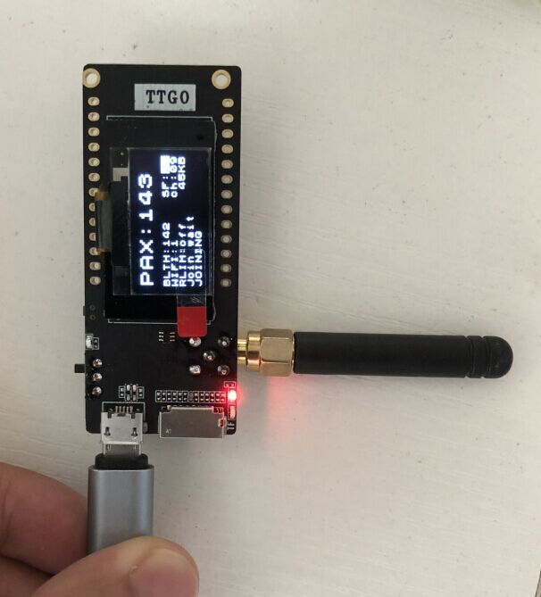
No switch for the OLED and I did already say I was not removing the power from any device.
I will be looking at removing the power from the SD card, if you could do that and keep sleep current under 10uA it would be a bit useful.
No switch for the OLED and I did already say I was not removing the power from any device.
I will be looking at removing the power from the SD card, if you could do that and keep sleep current under 10uA it would be a bit useful.
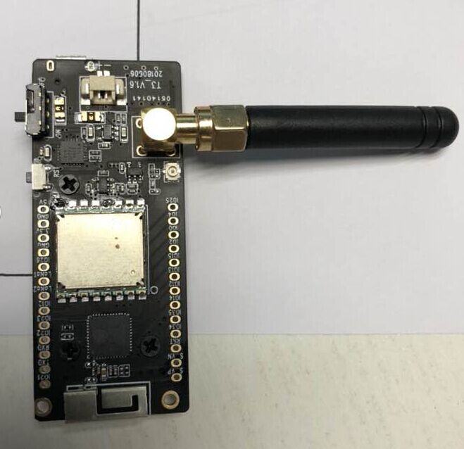
+++sneak preview+++
TTGO2.1 v1.6


Display flip comes by software 
Nice,
I ordered one yesterday so it will take some time before I can test it. Have you tested how fare it can send? How good the antena works?
Carefully studying the pictures reveals that, unfortunately, (when compared to V2) several pins and GPIO ports have been removed. The previous V2.1 was even worse in that aspect.
Do you know if you have to ‘flip’ a resistor if you want to use the U.FL instead of the SMA connector?
anyone with a TTGO LORA32 with GPS (think at least @Verkehrsrot and @Charles got one?) happens to know if there’s working ttn-mapper-code yet? ordered one and had hoped someone would have started working on that by the time it arrives, but it came sooner than expected  will be on a roadtrip to poland on monday which would be a nice … well … testdrive, but with my limited coding abilities it’s definitly too little time to get anything working from scratch by then…
thanks for any hints.
You would assume that any TTN mapper code (with local GPS) for ESP32 would work, with the correct pin definitions.
Details of my ESP32 shield build;
http://www.loratracker.uk/?p=810
http://www.loratracker.uk/?p=817
Deep sleep current with ESP32, SSD1306 display, 2Kbyte FRAM and SX127x LoRa device as low as 7.2uA, 8uA max.
Selectable sleep time up to 584,942 years.
“I would conclude that the SSD1306 consumes 0.5uA in when in sleep mode”
Have you tested only a singe SSD1306?
It would be interesting so see when you test multiple/different SSD1306’s.
I wonder what makes your SSD1306 module different from the 6 that I have tested which ranged from 7.0 uA to 32.5 uA in display off mode. A factor of 14 to 65 difference, 14 to 65 times more power usage in display off mode.
A program that demostrates for the ESP32 the folowing;
Putting the ESP32 into deep sleep.
Waking the ESP32 from deep sleep with a timer.
Waking the ESP32 from deep sleep using an IO pin (switch)
Sleeping a SD1306 display.
Sleeping a TC74 temperature sensor.
Sleeping a SX127x LoRa device.
Saving and using values saved in RTC RAM (survives deep sleep).
Checking and displaying on wakeup what event caused the wakeup.
Will be found here;
Sure I tested several displays.
The ones with the regulator on the back are a lot worse for sleep current.
A bit late for your trip but I have tested this one https://github.com/sbiermann/Lora-TTNMapper-ESP32 and quickly adapted it for the TTGO T-Beam without problem.
You will have to change some values in there : private TTN data, pins the GPS is hooked onto, lmic_pins depending on your version of the TTGO board. Apart from that it is ready to run.
That looks very interesting, thanks for the link.
Did you compile it un-altered ?
It fails to compile here, because the standard ESP32 setup in Arduino does not have the -fpermissive flag set and as a consequence you will get an error;
void LMIC_setSession (u4_t netid, devaddr_t devaddr, xref2u1_t nwkKey, xref2u1_t artKey);

invalid conversion from 'const u1_t* {aka const unsigned char*}' to 'xref2u1_t {aka unsigned char*}' [-fpermissive]And which LMIC library did you use I get quite a few undefined references in lmic.h, I am using this LMIC library;
Yes, sorry I forgot I had to fix those by removing the “const” modifier.
My own code is actually here but it is for the T-Beam : GPS RX/TX and some lora module pins are different from basic Lora32 TTGO.
The version of the LMIC I used is this one : https://github.com/matthijskooijman/arduino-lmic/releases/tag/1.5.0%2Barduino-2
Oh and also the T-Beam doesn’t have an oled display, so I removed everything related to that in my derivative.
Ah got it, as well as the consts you need these defines;
void os_getArtEui (u1_t* buf) { }
void os_getDevEui (u1_t* buf) { }
void os_getDevKey (u1_t* buf) { }
Unless you make a change in LMICs, config.h
Got it to compile now, thanks.
I have been using SSD1306 displays designed for 3.3V use snce that is whats needed for the ESP32. These modules do not need a regulator.
If your using the ones with the regulator on the back are they not designed for 5V use ?
You can remove the regulator and turn the displays into 3.3V ones.
Got this working, at least the application data on TTN console is decoding the payload correctly into latitude and longitude.
One issue to address with the software is that if the GPS is not connected (or fails to get a fix at startup) then the software sends a location of 0,0, so I guess a trap needs to be sure the GPS is providing a vaild and updated fix before transmitting. .