New are the latest ‘china’ 868-915 Mhz LoRa modules
This is the topic to discuss the different types ect…

New are the latest ‘china’ 868-915 Mhz LoRa modules
This is the topic to discuss the different types ect…
Got the ESP32/SX1276 868Mhz board from Aliexpress today but wow the WiFi antenna is super terrible. Whoever designed it has clue about RF.
I can tell they’ve also been trying different configurations for it, the one I got has a helical WiFi antenna - different from the Aliexpress photo - although it still has that terrible inverted F on the bottom too. But ultimately it’s not only bad antenna choices, the design is flawed by the antenna feedline as Angus from Espressif pointed out ( https://twitter.com/projectgus/status/922781274355351552 )
I saw this on picture before ordering, make me smile at first and wondering if screw was not in contact and what would the RF performance.
A quick an dirty fix could be put solder wire between PCB antenna and screw to make this screw act as antenna ?
(I’m kidding of course) 
Also just received 3 of these - https://www.aliexpress.com/item/SX1278-LoRa-ESP32-0-96-inch-Blue-OLED-Display-Bluetooth-WIFI-Lora-Kit-32-Module-Internet/32831131677.html - ordered 15th, arrived today.
Does anyone have more details on this? I have found - https://robotzero.one/heltec-wifi-lora-32/ and https://hackaday.io/project/26991-esp32-board-wifi-lora-32
I am looking for a schematic…
Not sure the designers - http://www.heltec.cn/ - released any schematic… Let us know if you find something please.
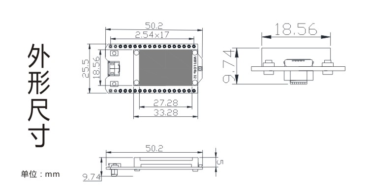
Edit : found technical drawings (dimensions) on taobao : https://www.sgshop.com/taobao/tao-bao/details?tbid=555750159003&cid=125190005&sptitle=Arduino物联网开发板+SX1278++ESP32芯片非模块OLED+WIFI+LoRa+32

What looks like a how-to-use manual : https://pan.baidu.com/s/1boT7atp
(Ask me if baidu is not friendly, I got a copy)
They sent me the Github project for the firmware
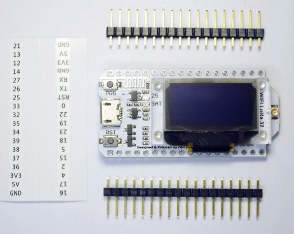
No schematic but you can at least find the pinout in the source code
// GPIO5  -- SX1278's SCK
// GPIO19 -- SX1278's MISO
// GPIO27 -- SX1278's MOSI
// GPIO18 -- SX1278's CS
// GPIO14 -- SX1278's RESET
// GPIO26 -- SX1278's IRQ(Interrupt Request)

#define SS      18
#define RST     14
#define DI0     26
The Arduino project only does raw LoRa, not LoRaWAN. I’ll try to port Pycom code to it, hopefully should get somewhere this week still.
Very good. I would really like to know if they connected DIO1
I think that LMiC v1.6 requires both DIO0 and DIO1
I think LoRa-node used in the Pycom fw only uses DI0.
I also found this patch by @Charles that supposedly lets you run without any DIOs at all? https://github.com/matthijskooijman/arduino-lmic/issues/24#issuecomment-228575898
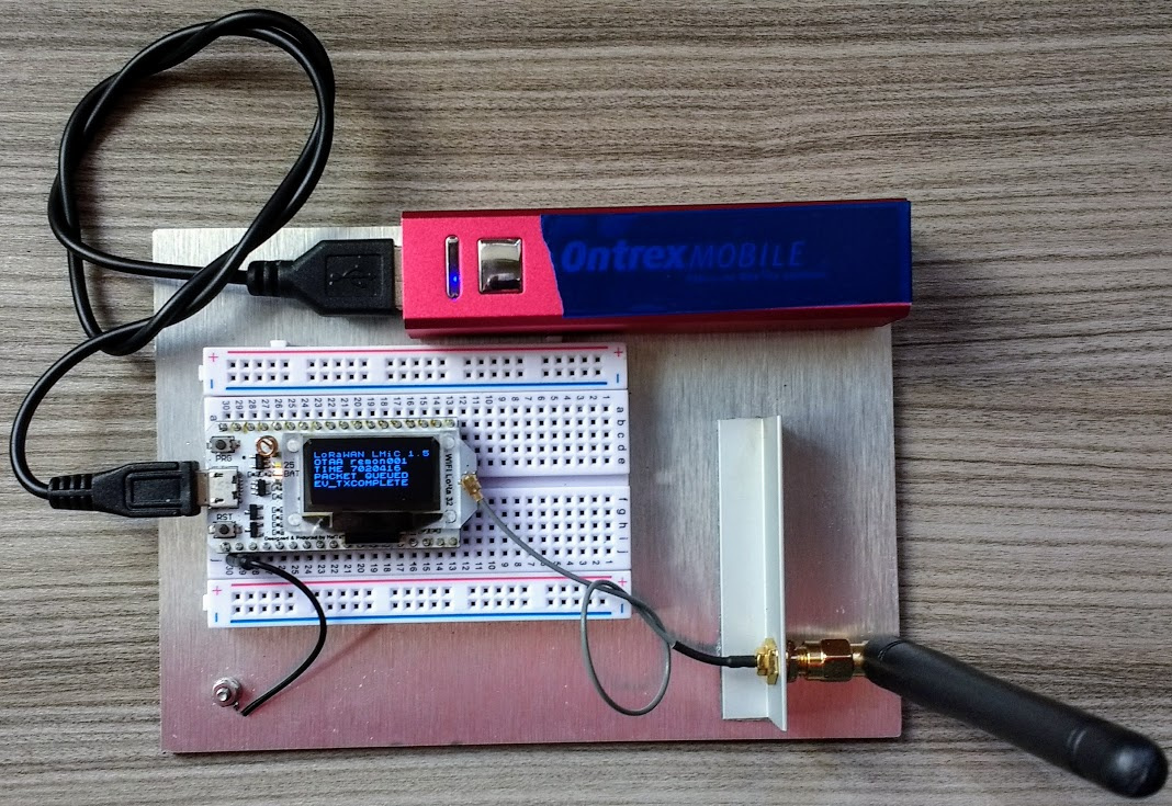
Thanks, I will go try. Using LMiC V1.5, setting DIO0 and DIO1 to the same physical pin allows the node to JOIN OTAA, but hangs there and does not pass through to JOINED or send any packets.
const lmic_pinmap lmic_pins = {
    .nss = 18,
    .rxtx = LMIC_UNUSED_PIN,
    .rst = 14,
    .dio = {26, 26, LMIC_UNUSED_PIN},
};I believe in the unchanged code DIO0 is triggered on TX and DIO1 on RX so the code may be missing the OTAA response (a RX) if you set it like that.
Does ABP work?
I will go back and try ABP. I have applied the patch you linked, to my local library, but I still get no further than EV_JOINING. I added the following to radio.c
// called by hal to check if we got one IRQ
u1_t radio_has_irq (void) {
    u1_t flags ;
    if( (readReg(RegOpMode) & OPMODE_LORA) != 0) { // LORA modem
        flags = readReg(LORARegIrqFlags);
        if( flags & ( IRQ_LORA_TXDONE_MASK | IRQ_LORA_RXDONE_MASK | IRQ_LORA_RXTOUT_MASK ) )
            return 1;
    } else { // FSK modem
        flags = readReg(FSKRegIrqFlags2);
        if ( flags & ( IRQ_FSK2_PACKETSENT_MASK | IRQ_FSK2_PAYLOADREADY_MASK) )
            return 1;
        flags = readReg(FSKRegIrqFlags1);
        if ( flags & IRQ_FSK1_TIMEOUT_MASK )
            return 1;
    }
    return 0;
}
added declaration in oslmic.h
u1_t radio_has_irq (void);
changed this routine in hal.c
static void hal_io_check() {
    uint8_t i;
    for (i = 0; i < NUM_DIO; ++i) {
        if (lmic_pins.dio[i] == LMIC_UNUSED_PIN)
        {
            // Check IRQ flags in radio module
            if ( radio_has_irq() )
                radio_irq_handler(0);

            // We've soft checked IRQ reading Radio register no need to continue
            // Setting this will exit us from for loop
            i = NUM_DIO;
        } else {
            if (dio_states[i] != digitalRead(lmic_pins.dio[i])) {
                dio_states[i] = !dio_states[i];
                if (dio_states[i])
                    radio_irq_handler(i);
            }
        }
    }
}
and commented out these two lines in hal_io_init
//ASSERT(lmic_pins.dio[0] != LMIC_UNUSED_PIN);
//ASSERT(lmic_pins.dio[1] != LMIC_UNUSED_PIN || lmic_pins.dio[2] != LMIC_UNUSED_PIN);
This all made sense tom me 
Update - OTAA works with the fix as described - it just started working while I wrote my last comment 
lora… not lorawan 

any idea what the currentdraw is ?
Current draw shows 0.07A running the default LMiC ttn-otaa sketch with code added to use the OLED display.
So far, I have done nothing to reduce power consumption.
Next steps are to move from Arduino framework to IDF with PlatformIO and then I will look to actively disable WiFi and BLE
ok tnx… 70 Ma is indeed a lot … need to trim that, maybe switch off the OLED when not needed…
@nicbkw Let’s discuss about some explanation on LMIC.
The way LMIC is coded is to check (in loop) for a pin change (software does not support IRQ yet) on each declared .dio pin. Then, if one pin has changed, stack is reading software IRQ register of RFM95. Reading RFM95 IRQ internal register will expose all IRQ available (so all DIO0 … DIO5).
That is why I created my “No DIO” patch (and also because I didn’t had any free I/O). this patch read this register and can work without any DIO pin connected, the con is that on each loop, we do SPI transfer to read IRQ register. It’s not fulltime task but it’s done only during LMIC transmission (send and receive) so it’s not so bad, and works !!!
So if you are using only one DIO pin connected this will do twice the check on same pin
.dio = {26, 26, LMIC_UNUSED_PIN},
so you can leave as follow (same result)
.dio = {26, LMIC_UNUSED_PIN, LMIC_UNUSED_PIN},
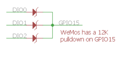
Another solution is to OR each DIO pins with diodes to trigger a IRQ on any DIO change (once again this is possible only because LMIC read RFM95 IRQ register on any DIO change. And since they are OR’ed, one will be enough.

Hope this bring some clarification ![]()
PS : has @jmarcelino will have excellent relationship with pycom, may be he could tell us how DIO are connected on Lopy? We can also open Lopy to see or look into micorpython stack code !
ESP32 is very versatile, has a sophisticated watchdog, but might not be ideal as a very low power data logger.
Thanks very much for this explanation - I was very pleased when @jmarcelino pointed me to your single interrupt polled solution as it works!