Most of the LoRa modules available in the market require antenna to be used with the board.
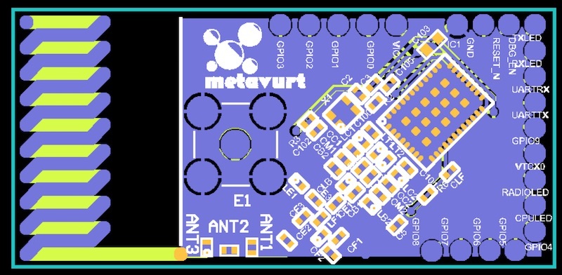
How can we design PCB Patch antenna for 865 to 868 MHz, so that our LoRa end nodes need not to have additional antennas ?
Most of the LoRa modules available in the market require antenna to be used with the board.
How can we design PCB Patch antenna for 865 to 868 MHz, so that our LoRa end nodes need not to have additional antennas ?
what range do you expect to get with that? because im sure it wont be alot…
We get satisfactory results from this design:
http://www.ti.com/lit/an/swra416/swra416.pdf
Or you can try this which should avoid a matching network
http://www.ti.com/lit/an/swra228c/swra228c.pdf
But really there are a lot of factors for a PCB antenna. You’ll likely need specialist analysers: VNA, spectrum etc to get it right, but it is possible.
The Parameter that i need to set is power not range. Range will be maximized automatically.
In my city, LoRa network is deployed for devices emitting 20dbm. Thus the patch antenna must support it. Also, if the gain of antenna can be 2-3 dbi, then it would be great.
Thanks jmarcelino…
Will definitely go through those and try to figure out a solution.
Someone published a Launchpad Boosterpack for the RN2483 module with a PCB antenna which was actually lab tested, have a look at:
https://e2e.ti.com/group/launchyourdesign/m/boosterpack/666416
The design is available to download there (you’ll need Altium to edit)
Thats great help.
I am on it…::))
You said “We get satisfactory results from this design: http://www.ti.com/lit/an/swra416/swra416.pdf”. Does this mean you have actually manufactured and used this reference design?
Yes I used this in one of my Sigfox designs, but I haven’t done extensive lab testing other that “it works” for me and test sites. I expect the performance to be similar on LoRa.

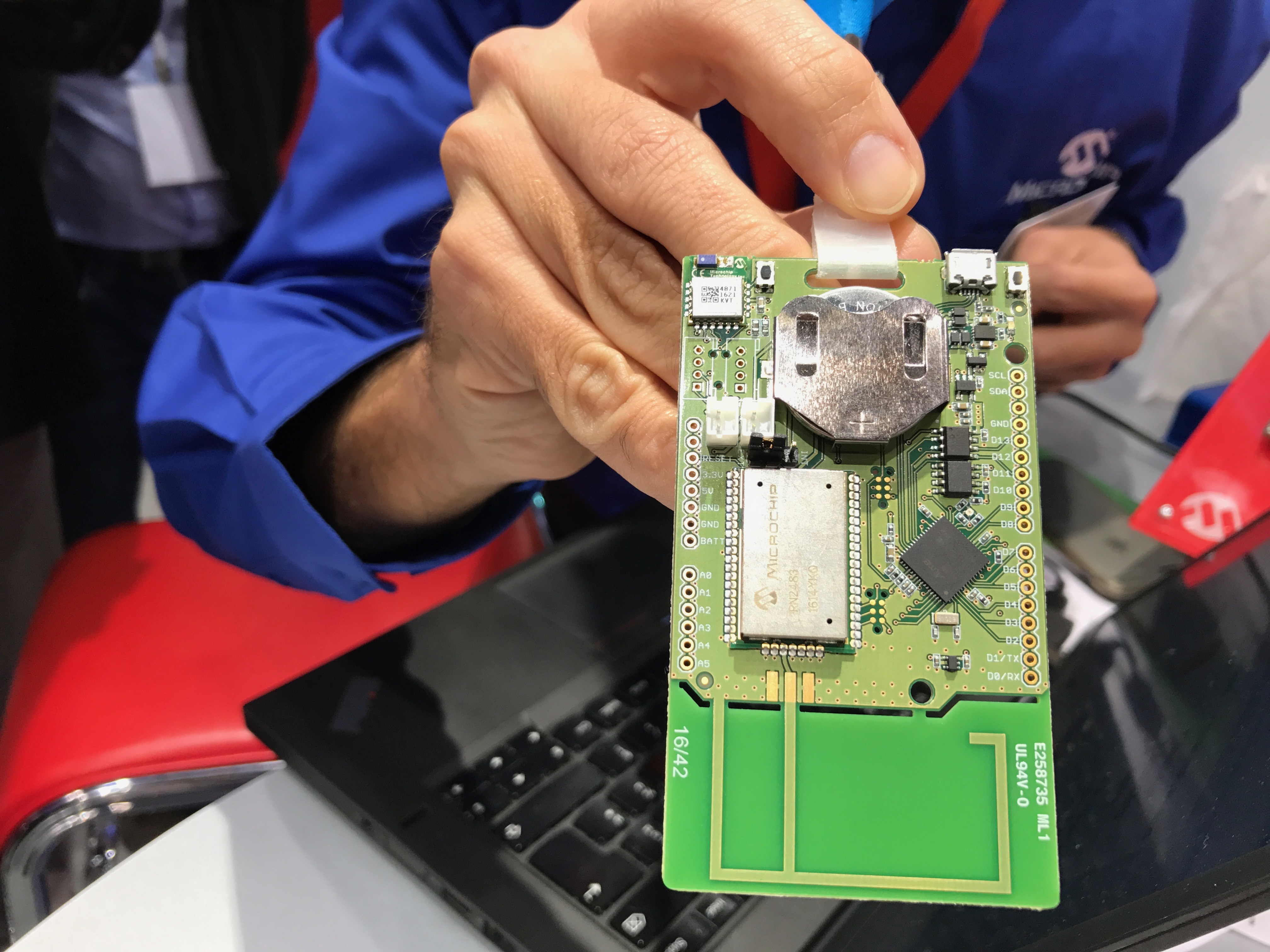
Texas Instruments is also shipping thousands of units using this design on their new 868/915Mhz + Bluetooth LE Launchpad: http://www.ti.com/tool/launchxl-cc1350
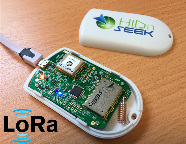
Having said this PCB antenna design is fussy and depends on many factors, ie it only takes the fiberglass fibers that make up the PCB structure being aligned differently to affect performance. It’s also true that our friends at HidNSeek have achieved some impressive range records - last one 900 Km, likely harnessing tropospheric ducting - using a cheap, small and rather easy to mount helical antenna like below, so make sure you consider all options.

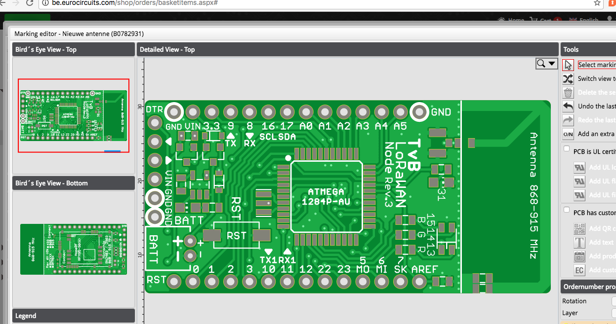
I’m also developing a PCB antenna version (868-915 MHz) of my node. My boards are ordered this week so I’ll put them to the test soon! I hope to get satisfying results 

The new version is based on my previous designed node and supports RFM9X + RN2483 modules. See here: https://eth0maz.wordpress.com/2016/08/21/the-new-lorawan-node-is-alive/
Thanks for sharing.
Can you please share the design files of the Patch antenna?
I first need to verify if this design works in the real world (I don’t believe all simulation software out there ![]() )
)
After that I can post it online ![]()
Yeah, that would be great for every enthusiasts out there.
@eTh0maz What was the final outcome of the PCB antenna design? Did it work fine or is the performance rather bad?

I didn’t have much time but I had the antenna design tested/measured. The results are satisfying but not perfect yet.
Ideal for short range but this antenna design won’t reach more than a couple of km’s.
The frequency is a bit off the centre (about 30MHz) to match 868MHz so that’s going to be fixed in the next hardware revision.
The node with onboard antenna is still work in progress.
In the meantime I found some time to write a post with the first impressions and the conclusions from some range tests with professional gateways in the field.
Do you have any source for this design ?
sorry No I don’t