The wiring
The wiring should look like below. The black/white wire is a white one in the pictures.

Well, that’s it. This tutorial assumes that you will mount them on top of each other, which is easier than it looks like. In case you still prefer not to do so you can use so called ‘prototype PCB boards’ to mount them next to each other. Regarding the wiring I suggest not to change the mentioned wiring since this fits the LMIC library wiring and it also simplifies using each other’s software. At the end of the day that TTN compatibility may be more important than a wire that’s possibly routed in a slightly smarter way.

Remark: if you consider modifying your arduino to decrease the power consumption you should do this before you start with the assembly. Across the internet several options are described like unsoldering the led or voltage regulator, but that’s beyond the scope of this document. Besides perhaps it’s better to keep your first node as simple as possible and skip this kind of optimization.
The wire should be stripped with a few mm's on one end, and about a centimeter on the other end. Exceptions are red and black where an additional 3 or 4 cm may be useful because you may need those for sensors or power supply.
Leave this length of isolation:
orange/yellow/red: 20mm
black: 25mm
white: 16mm
blue/purple: 14mm
brown/grey/green: 4mm
Start with orange, yellow, black, red and white. Solder these to the RFM.

Bend in shape

Push the wires through the Arduino holes. Bend the ends to make sure they stay where they are

Now add the blue and purple wire. It's best to first only solder them to the RFM and on the arduino side just bend them to keep them in place. Once all these three are connected to the RFM it's time to solder them to the arduino. These wires are the exception of doing so at the very end because they will be subject to some more tension when the RFM is located in it's final position. Remember: the final position of the RFM vs the arduino depends on how you solder these wires so make sure they are as you like them to be. It's a good idea to bend the blue wire a bit to keep A0 accessible.

Bend the RFM upward on the other side so it's a bit diagonal. Add the brown, grey and green wire. Only solder the RFM side at this time.


Now it's time to place the RFM in it's final position. Fold the wires in such a way that they remain where they are.

For the VCC and the GND it's in particular important that you'll be able to solder additional wires to it when needed. So make sure to bend the wires in such a way that they act as a kind of hooks, in order to avoid that they will slip away when the solder is fluid again.

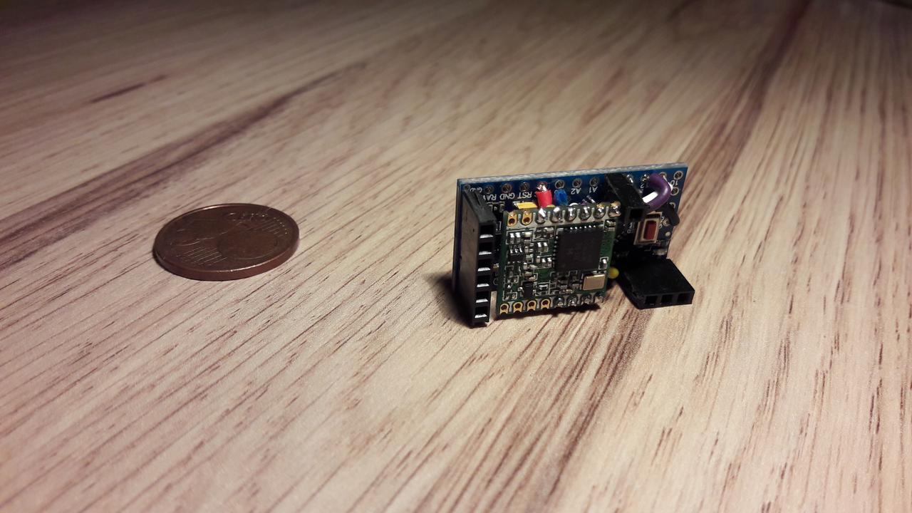
Now it's time to do the final soldering and cut the wires (except red and black perhaps). Add some headers for easy interfacing with sensors and the result should then look like this:

Now don't forget to solder your antenna to the header marked with 'ANT' in the wiring diagram. Once you've done and after uploading software the node works!


