no … why ? problem ?
Having issue with RN2483 and SF12 on OTAA and there are a number of threads on here with join issues (seems related to the nodes not receiving the gateway join accept), one of the forum threads ended with ‘the RN2483A could resolve the problems’
Isn’t starting communication on SF12 prohibited in TTN?
I thought you could start an OTAA join on any SF
@ what temperatures can I expect problems with the ’ old ’ RN2483 ? 
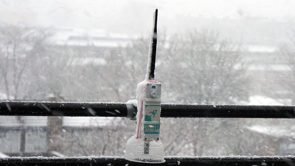
This one got off my work bench and is now in operation in the “wild”.
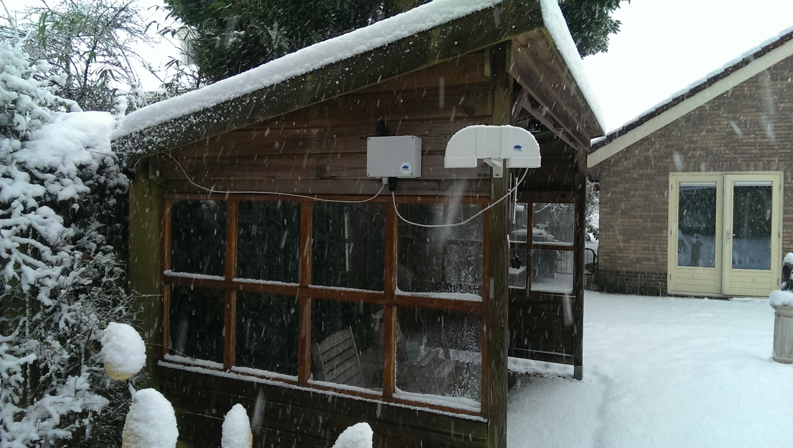
Are those a gateway and a weather station?
Can you share some data on the temperature: outside vs in-the-box?
I would have to prepare my outside gateway for spells of seriously cold weather and any data would be very useful.
@jprttn The box on the left is a TTN Uno with a specific designed shield for the SDS011 dust sensor in combination with any i2c sensor. The “horn” on the right contains the sensors. Yes, the sensor housing is very “BIG” compared to the sensor but it was availabale almost for free. There is no gateway on the picture.
I have only temperature measurements outside. There is no temperature reading in the box. Sensor readings can be seen here: https://cayenne.mydevices.com/shared/5a2d52113c0fd502a0bff597
I do expect the temperature inside the box to be the same as outside. I hope the answer is helpful anyway.
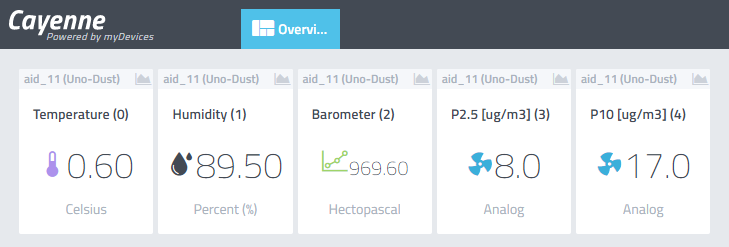
nice touch… the little fan icons 
* also curious how long the sensor fan will last in this climate
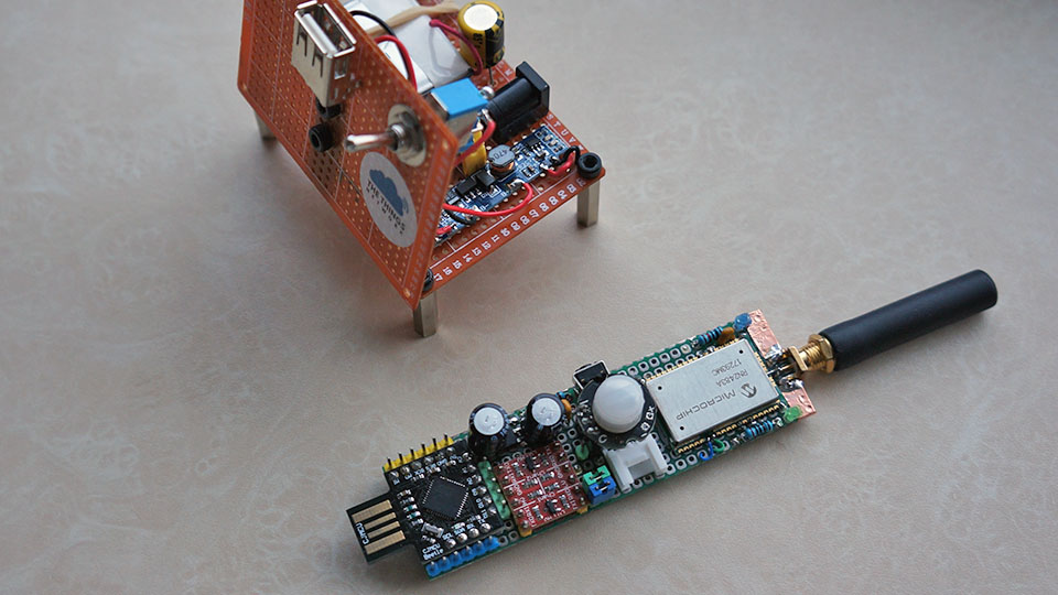
LoRaLarm stick & docking station 
Mine stopped working below -1 dgr. But when it gets above 0 dgr. it starts again.
I’m using it now for indoor measurements. But that was a very old RN2483 ![]()
yes this one to, the rn2483 (without the 'A") and firmware is updated to 1.03
stil working here after 48 days on a single AA but I made a little construction mistake
so humidity gives 100% all the time.
- nice to know that its starts again by itself

MC8775 very old 3G modem sells for 10 euro on ebay on average 
 . Hacked up to USB modem:
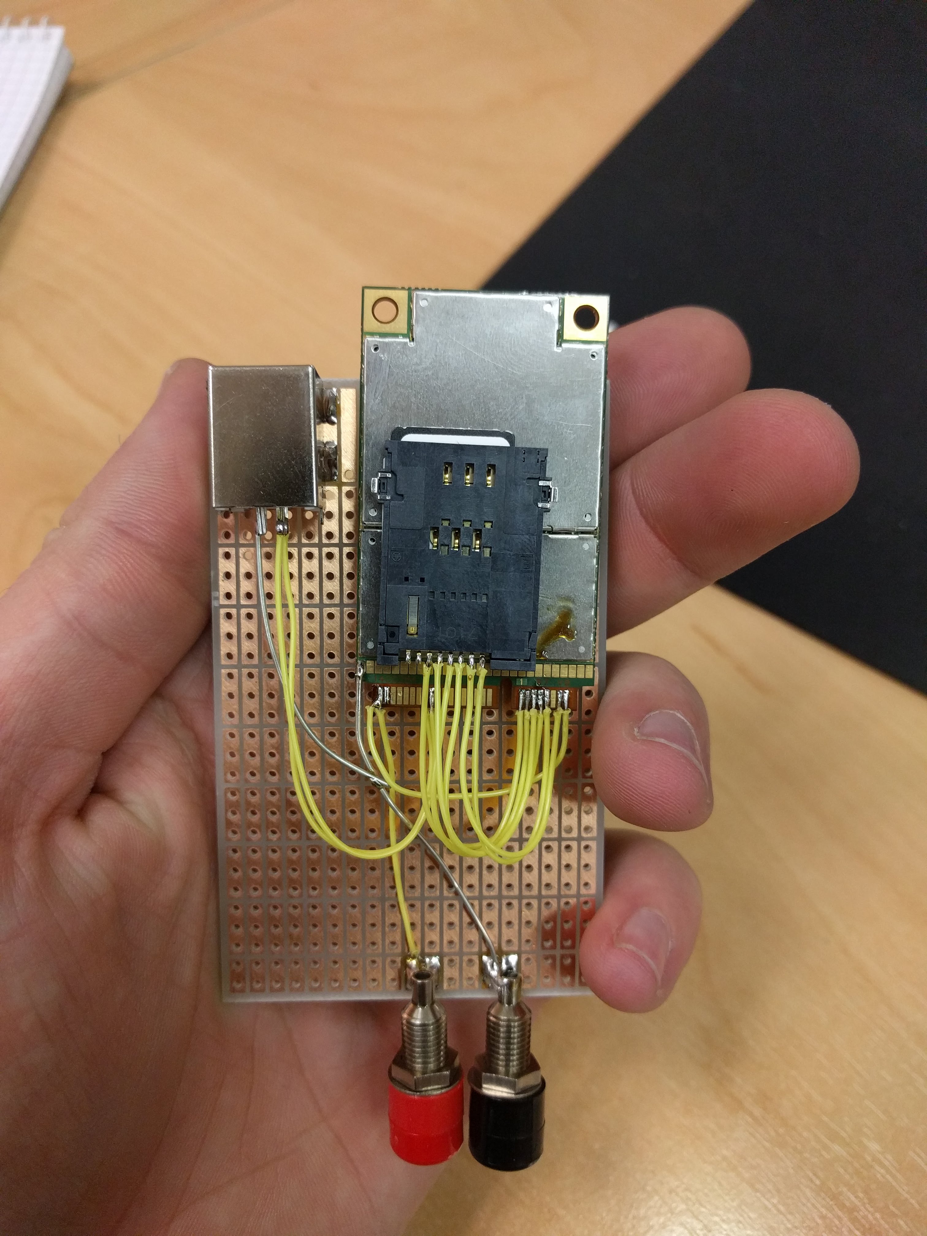
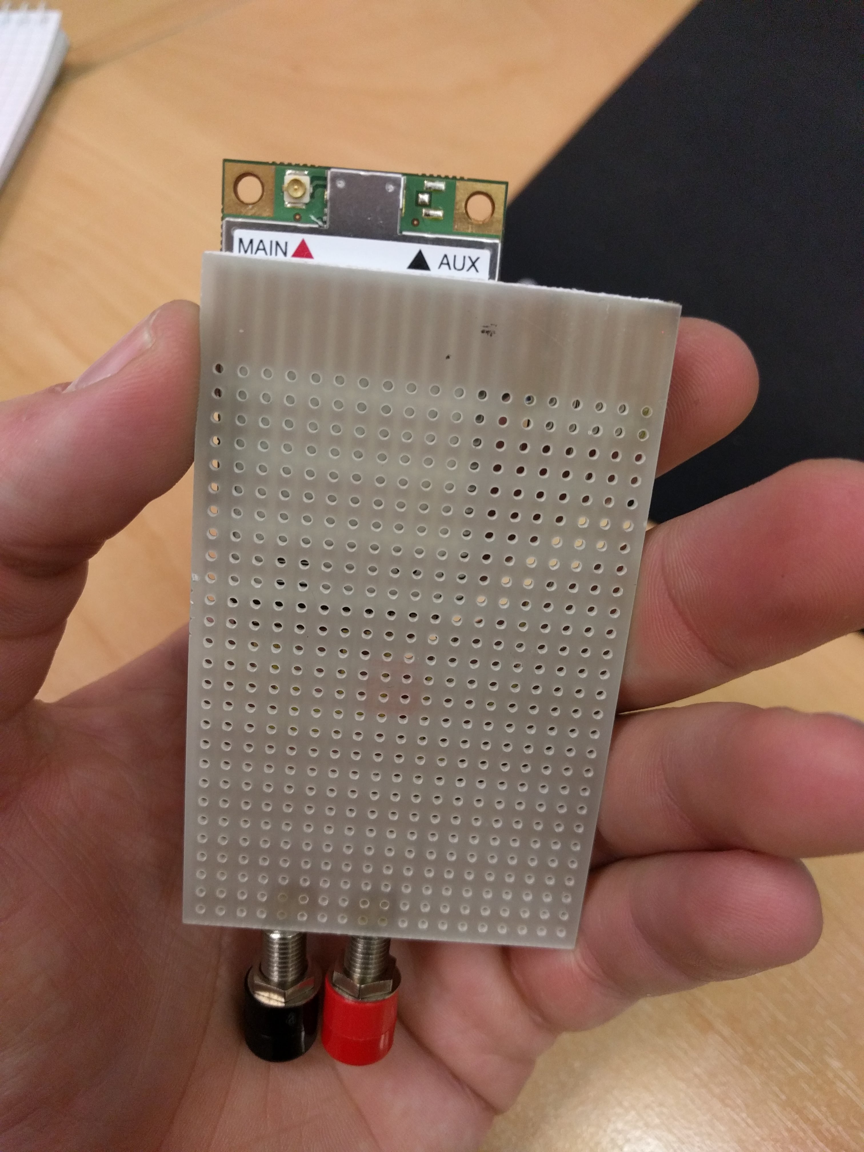
Connected the pi RAK combo to the modem and with a ping of 180ms the mp_pkt_fwd runs and manages OTA and regular packages:
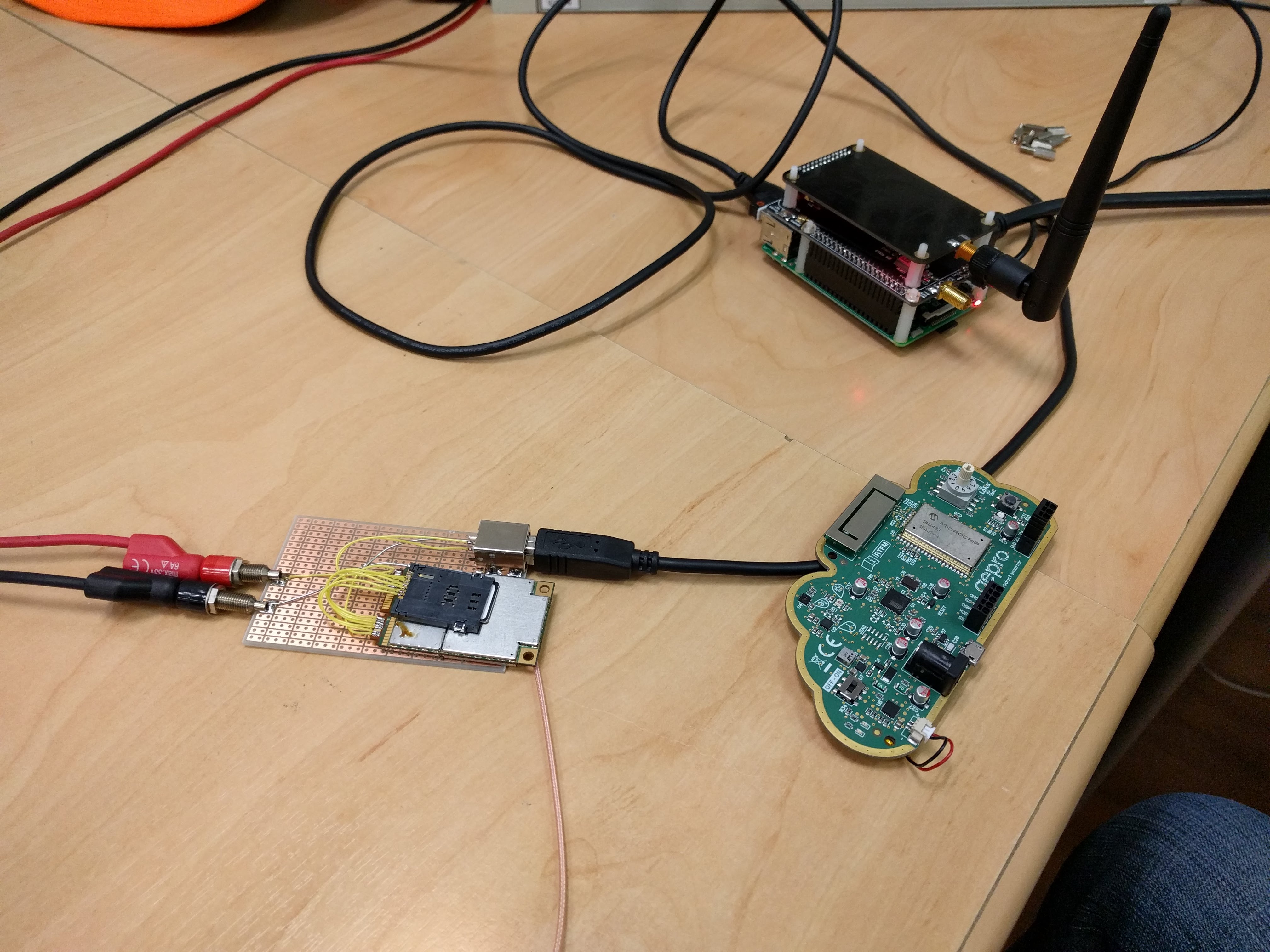
A speedtest on the Pi shows 1.8Mbit down and 0.3Mbit up, I am impressed  .
.
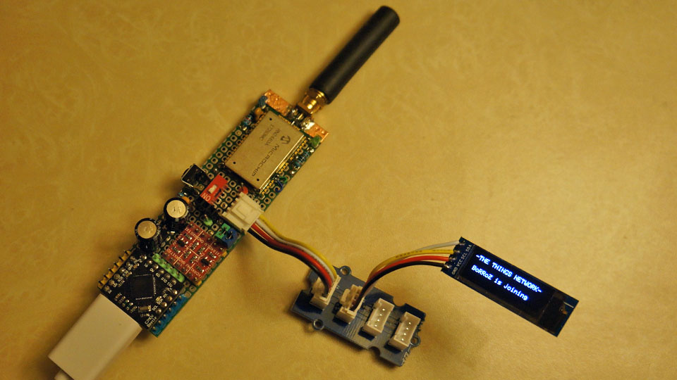
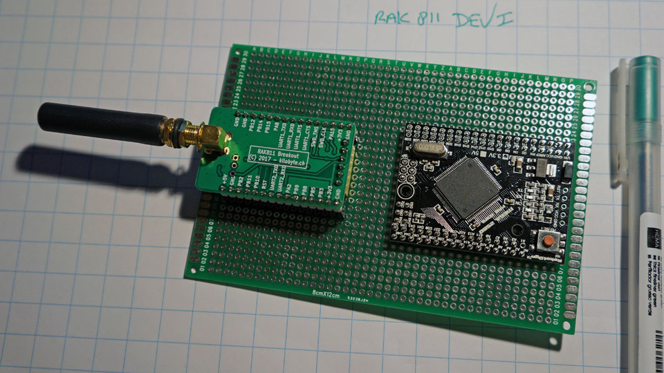
how to setup a test environment for the RAK811 ?
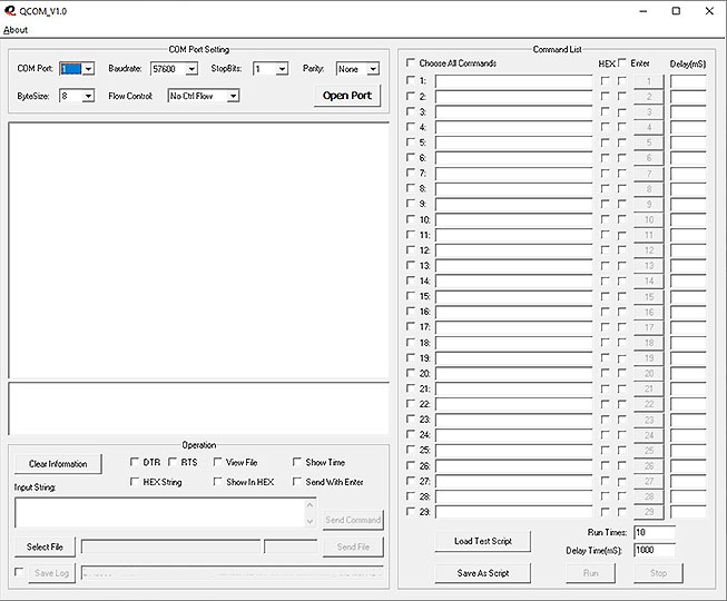
have an old terminal program that can save a sequence of AT commands, so I can connect
the RAK811 direct to a USB serial and test before programming the mega mini.
eh, veroboard?
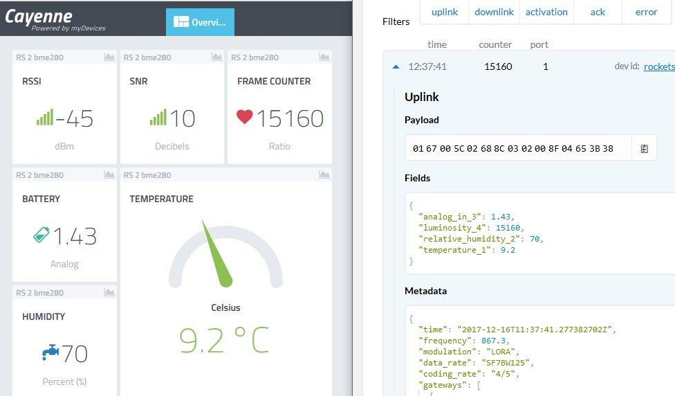
the rn2483 node ‘survived’ the bad weather and we are in day 53 on a single AA without missing one frame.
‘framecounter’ on the left is a value coming from the node and increased every transmission and 'counter on the right is a number from the TTN backend… they should remain the same.
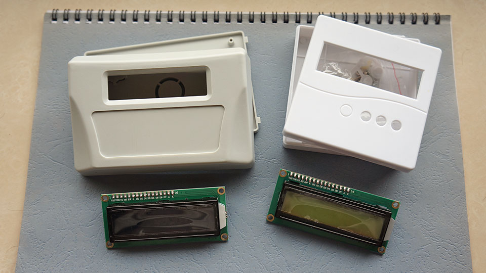
parts for an ‘in between projects’ project arrived : a digital knitting row counter for my sister.
will get an USB keyboard connection, a 16x2 display, battery, processor and RTC and some buttons.
I’ve realise now that I have never connected a ‘normal’ keyboard to an arduino project as an input device 
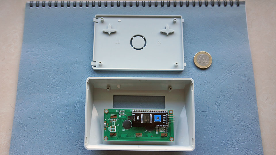
decided to use this enclosure, it’s nice finished and you can mount a 16x2 display without drilling mounting holes.
I have started to use Cayenne following your example presented here - it is really easy and quick built-in integration (although I miss some data types like “date” or “time” for example…).
Were you restarting the frame counter when temperature/humidity sensor was replaced?
Does this board keep the state of variables during the deep sleep phase?
- I didn’t replace the sensor nor the frame counter , it’s still the bme280
- this board uses a different technique for sleep, it’s not the processor that wakes up and then wakes the radio module RN2483 but the other way.
that saves some energy, especially when you have long sleep periods (like one week)
the processor doesn’t have to wake up every 8 seconds to increase a counter and get back to sleep, it sleeps all the time until woken by the rn2483.
I use it for 5 min #define SLEEP_PERIOD 300000 // max = 4294967296 - 49.7days
see test code here
ttn.sleep(SLEEP_PERIOD);
sends the rn2483 to sleep
attachInterrupt (digitalPinToInterrupt(2), awake, LOW);
set the interrupt for the mcu on pin 2
when the rn2483 wakes up it sets the Tx line low, on that signal the MCU wakes
LowPower.powerDown(SLEEP_FOREVER, ADC_OFF, BOD_OFF);
set the MCU to sleep
so at this point in the loop both are a sleep, when the rn2483 wakes up, it wakes the processor and
returns in the loop were it start again with
readSENSORS();