
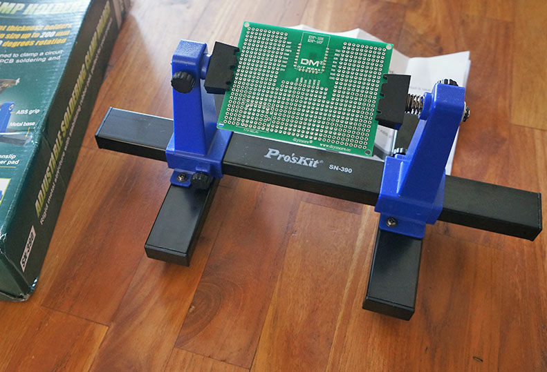
cheap Adjustable PCB Holder
That’s strange it stopped at 1.25V looks like 1.25V shoud be fait enough to run with the DC/DC step up used, did you just tried to reset the board ? just curious because I had some transmitting below 1V battery
I added some 100uF caps to the output of this kind of DC/DC step up I made to get peak current fine. worth trying ![]()
I’d put a fresh battery in and it worked again… so the hardware is ok.
model 2 under test has a 3v battery and a better dc/dc converter 
should last more then a year
I put the empty battery back in and watched the application console…
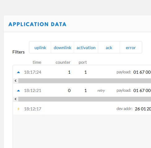
it’s alive again… a zombie node … aaaaargh
@Charles … we had this integer overflow… luckily the nodes own frame counter started at zero and didn’t crash the running application … but could that be a problem in some situations (328P) ?
moved it to the other side of the room… signal is picked up again at ca. 13 km … so it did’n lose any rf power
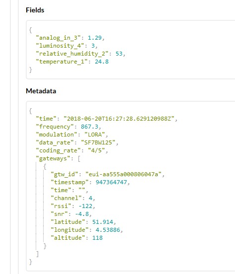
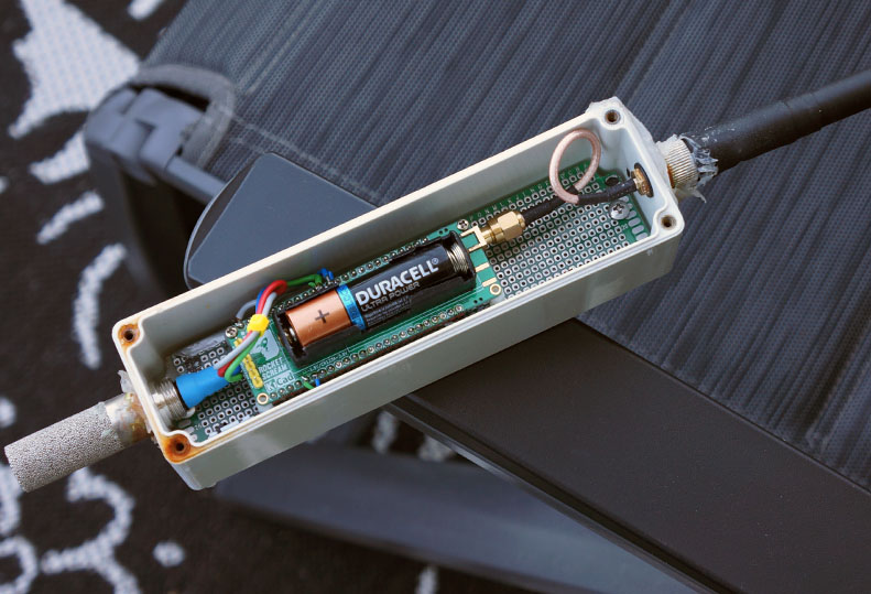
The Transmitting Dead 
now its ’ realy ’ dead  @1.17 v
so it transmitted 83565 frames - 6864 hours - 290 days on single AA
hereby close this live test.
Ah, that PCB is still unused. 
(Same here.)
The internal resistance of the battery must also be taken into consideration. During the burst transmission, more current is needed and hence a larger voltage drop within the battery itself is sometimes too much to sustain the output voltage. Every time, after a transmission and node going to sleep, the battery voltage will have some time to recover a bit (in Rob’s case where the battery is removed it is more obvious, I don’t think it would last that long after the restart). I did some fine tuning to the stability of the boost converter control loop to help to increase the stability during transmission and also lower down the minimum input voltage.
Hi Phang,
here you see the voltage drop during burst @ this moment … it’s not that much , about 55 mV ?
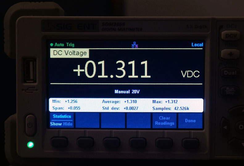

The drop is probably across the reverse protection MOSFET resistance (RDSon) and battery internal resistance. Also MCU ADC is measuring the battery voltage after the reverse protection MOSFET.
yes but I’m meassuring ON the battery … (can’t reach the other side of the PCB now)
at the same time the console is open… so when the dc/dc quits, hence no lorapackets any more, I could see the battery voltage at that point ?
anyway… it’s no longer that important I think … just curiosity
Add a larger capacitor near the radio IC
tnx but off course … that’s not the point at this moment, we are trying to find out why and at what point exactly the dc/dc converter stopped yesterday , or maybe the rn2483 crashed or the 328p.
I must have missed something in the sequence you are following. I thought you were still trying with the old battery. If that was the case then I also think the internal resistance of the aged battery is the culprit.
I am ready to go with the same project but for Pi Zero W, Charles’ PCB and excellent instructions except that my RAK831 is still at large!
For a smaller gateway go RAK833.
But then @Charles first will have to solve a new challenge: make an RPi Zero adapter board for it. 
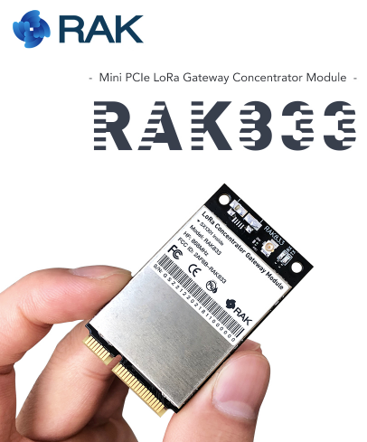
Really impressed with these. Hope mine arrives today and along with my PCB and own designed high gain antenna hope to create a compact outdoor waterproof gateway with POE and Solar connections.
I’ll just leave this here… 
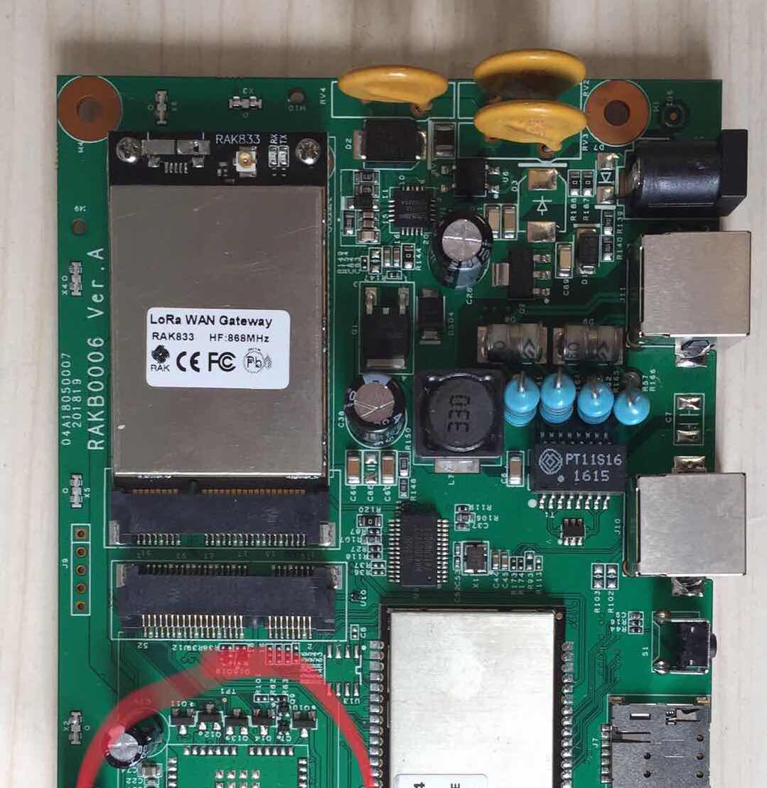
lol… yes I’ve seen that vid… the scope I can’t afford in this life 