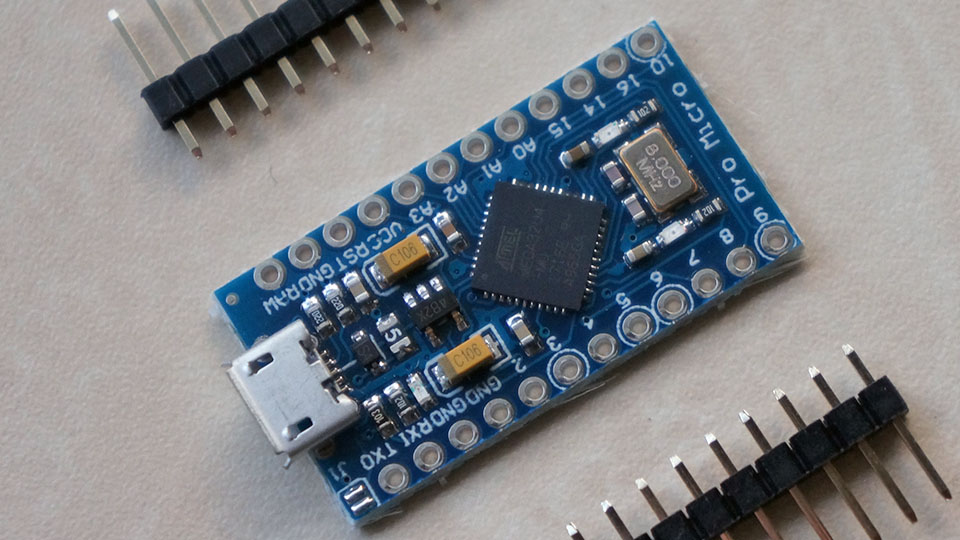
Leonardo Pro Micro ATmega32U4 8MHz 3.3V !
so direct connection to RFM95 / RN2483 possible ? a mini TTN node ?
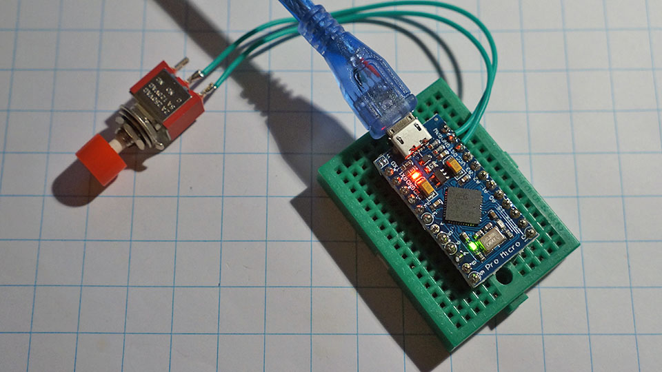
always run BLINK to check module 

Leonardo Pro Micro ATmega32U4 8MHz 3.3V !
so direct connection to RFM95 / RN2483 possible ? a mini TTN node ?

always run BLINK to check module 
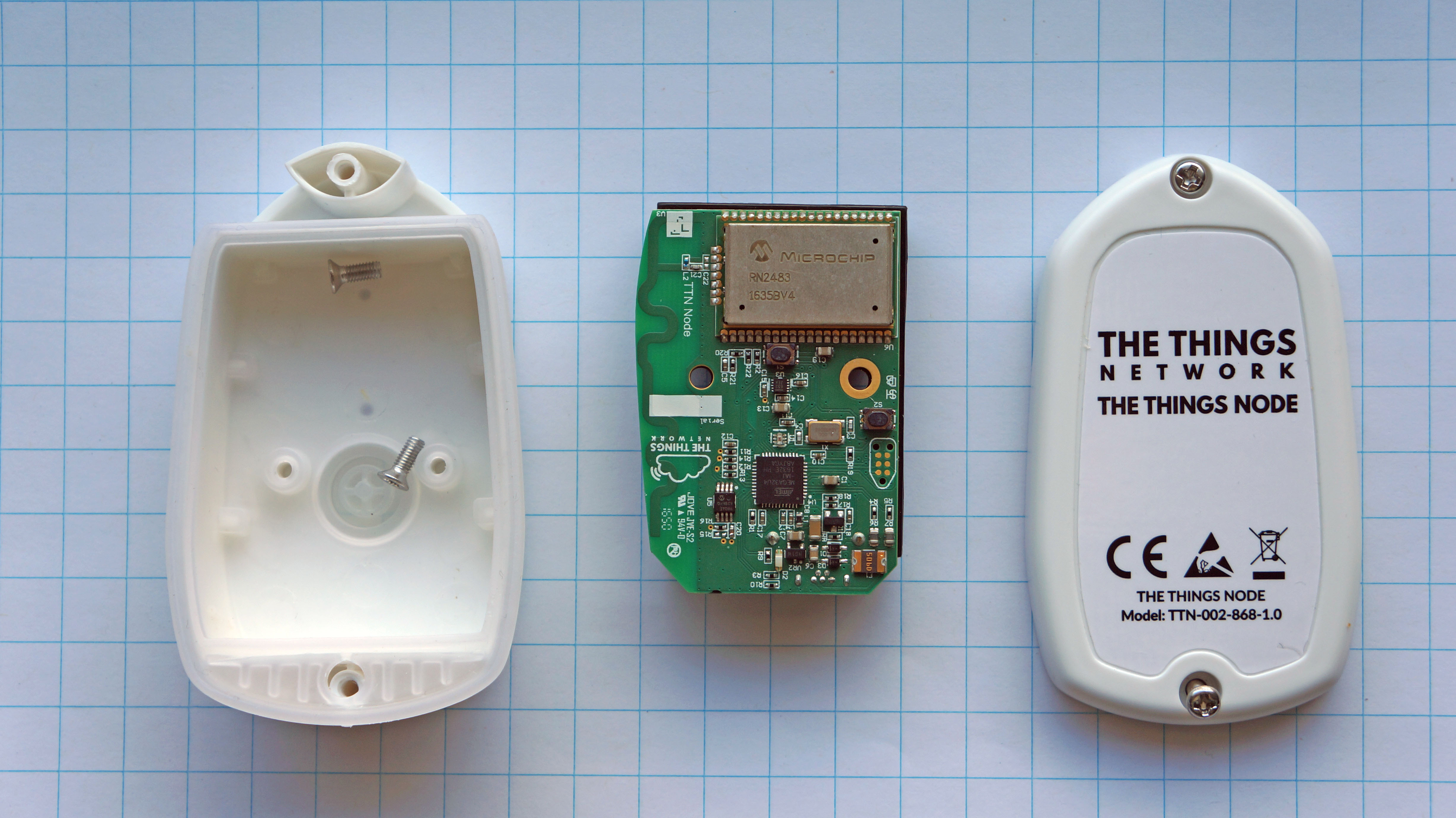
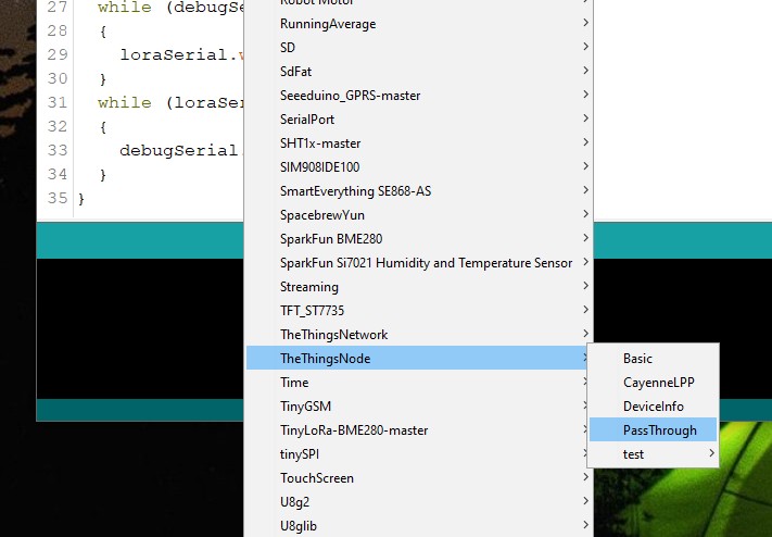
after loading the passthrough sketch in the TTN node
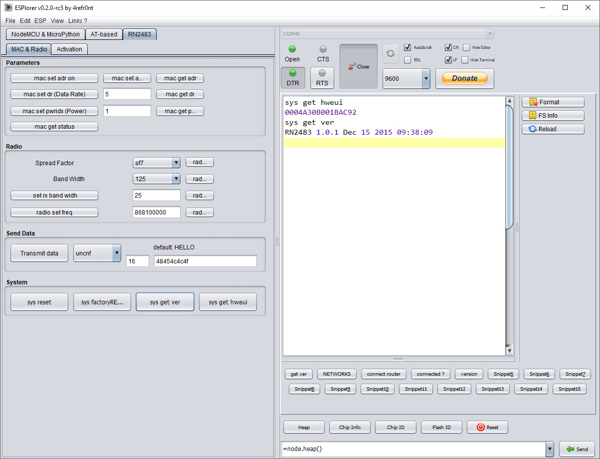
I started this ESPlorer V2… nice free tool for the ESP8266 and now extended with preprogarammed buttons for the RN2483
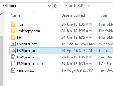
to start just double click ESPlorer.jar
tool seems to work
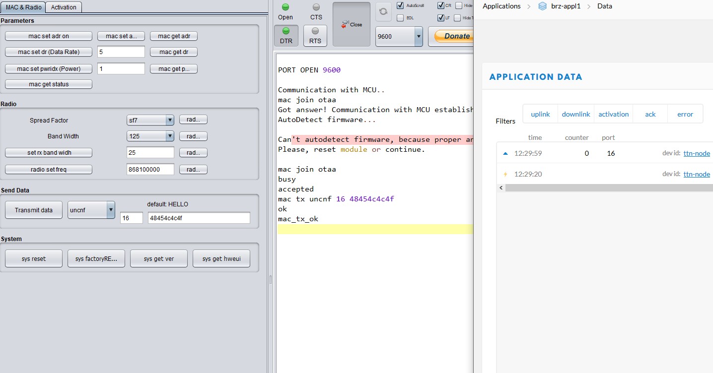
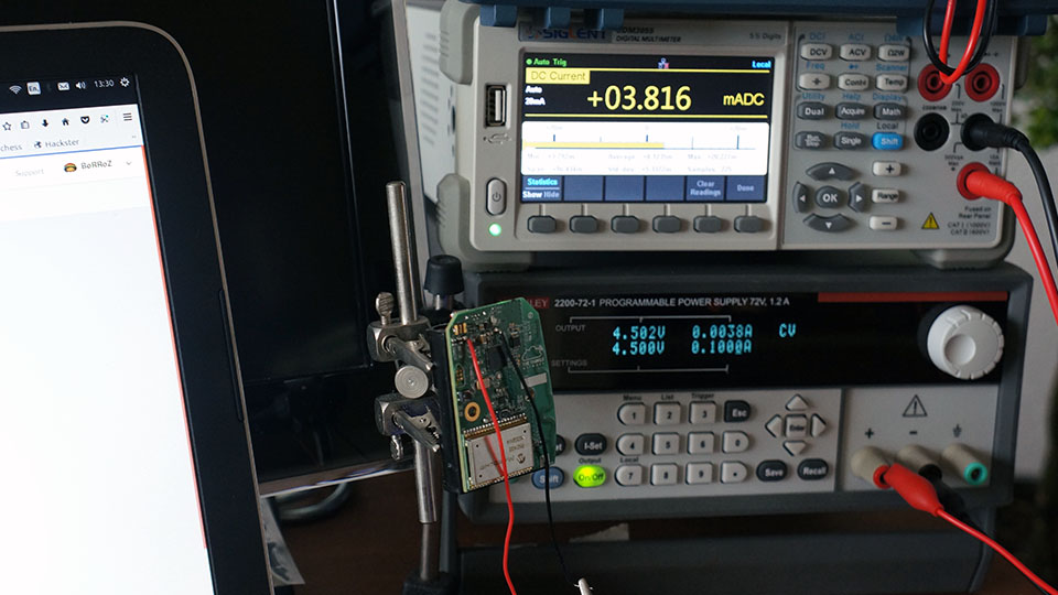
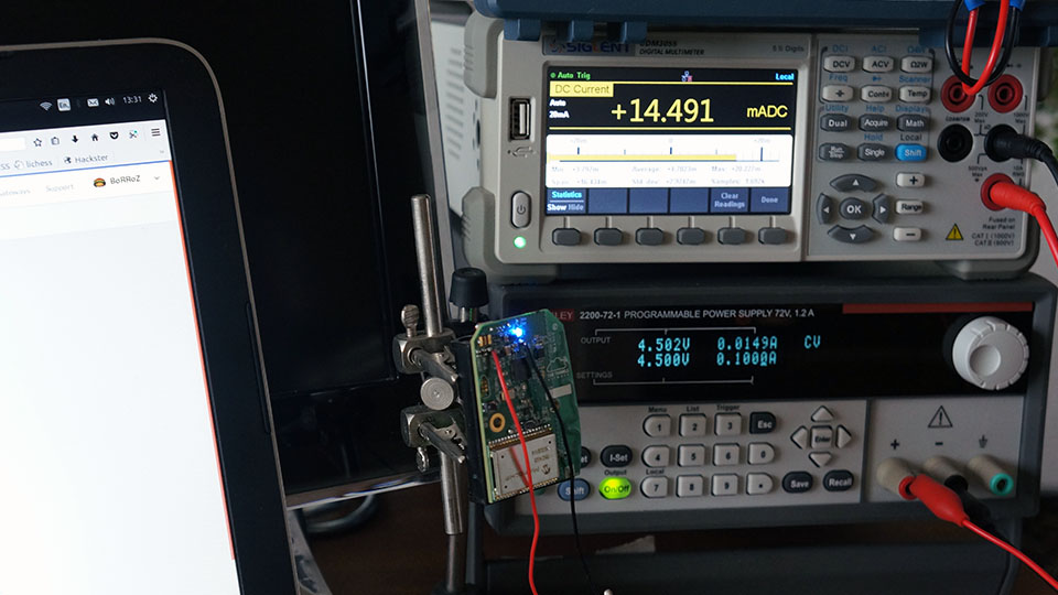
testing TTN node with RN2483 firmware 1.0.1
loaded with the basic sketch
Rx = 3.8 mA
Tx = 14.5 mA
first conclusion … don’t leave the basic sketch in the node with the batteries 
I will have a closer look at the ‘sleeping’ code … and ask @Charles and @rocketscream , the low power specialists, for advice how (and if possible) to improve this TTN device
now I will upgrade the RN2483 firmware and test again :
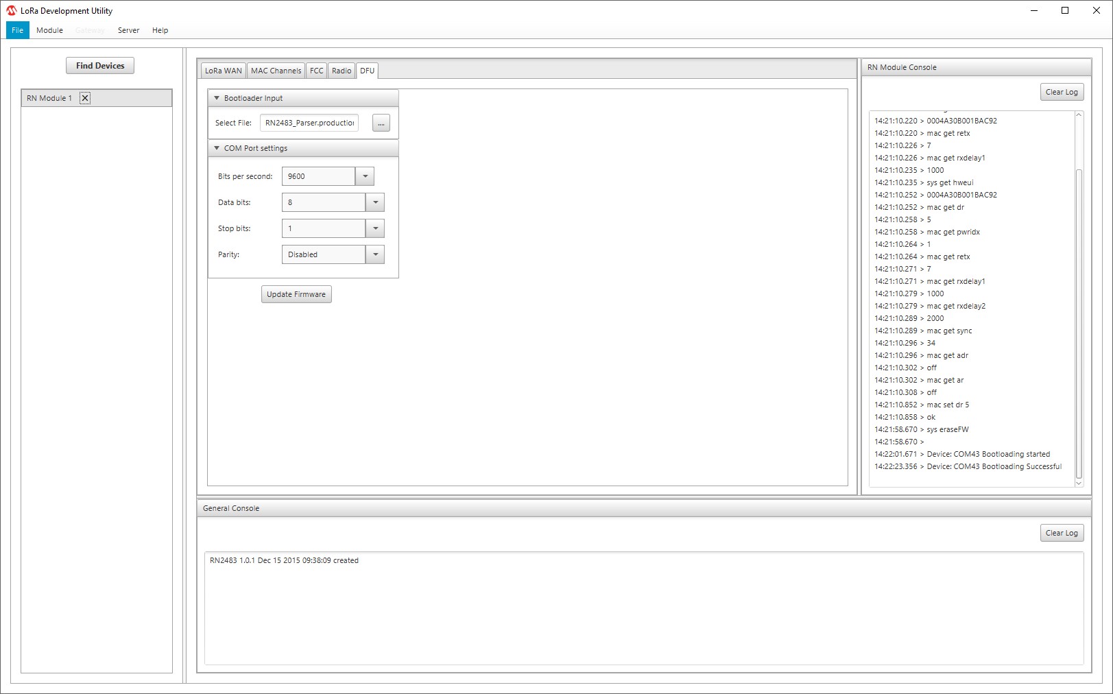
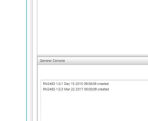
ok firmware updated to 1.0.3 with the passtrough sketch and the semtech tool
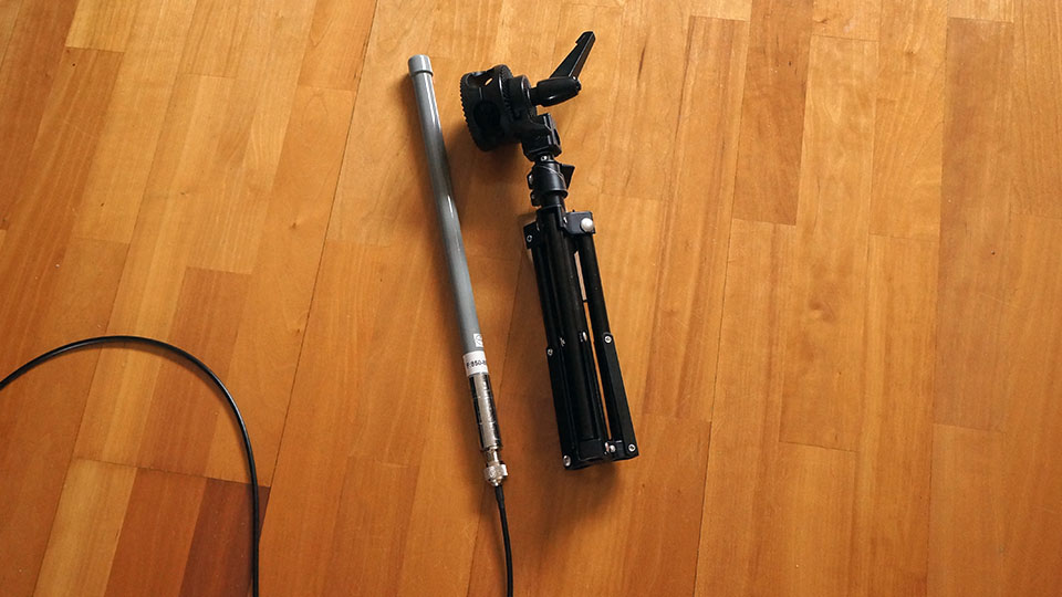
fits without tweaking
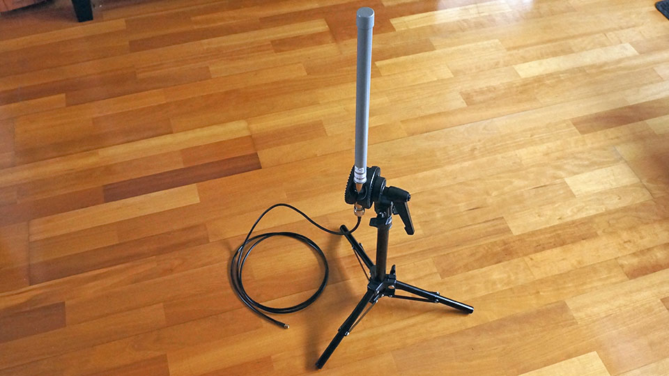
The idea is to make an simple (work) table stand for testing different antenna’s and to make it portable.
I found on eBAY this Studio Photography Light Flash Stand Support Tripod and this Studio Lamp Boom Arm Reflector Single Swiveling Grip Head Bracket Clamp Holder
nice antenna.
a recommendation?
any measurements?
it looks like it actually sends the sleep command to the RN module, and also triggers the function to put the uC in sleep mode. But I also can’t get it below 3.x mAh, even with bare minimum code. Maybe there’s a HW voltage regulator drawing the remaining current?
we need the schematic…
everything is published now https://github.com/TheThingsProducts/node/tree/master/hardware 
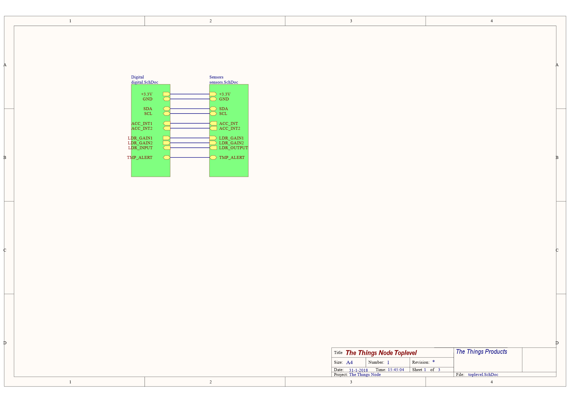
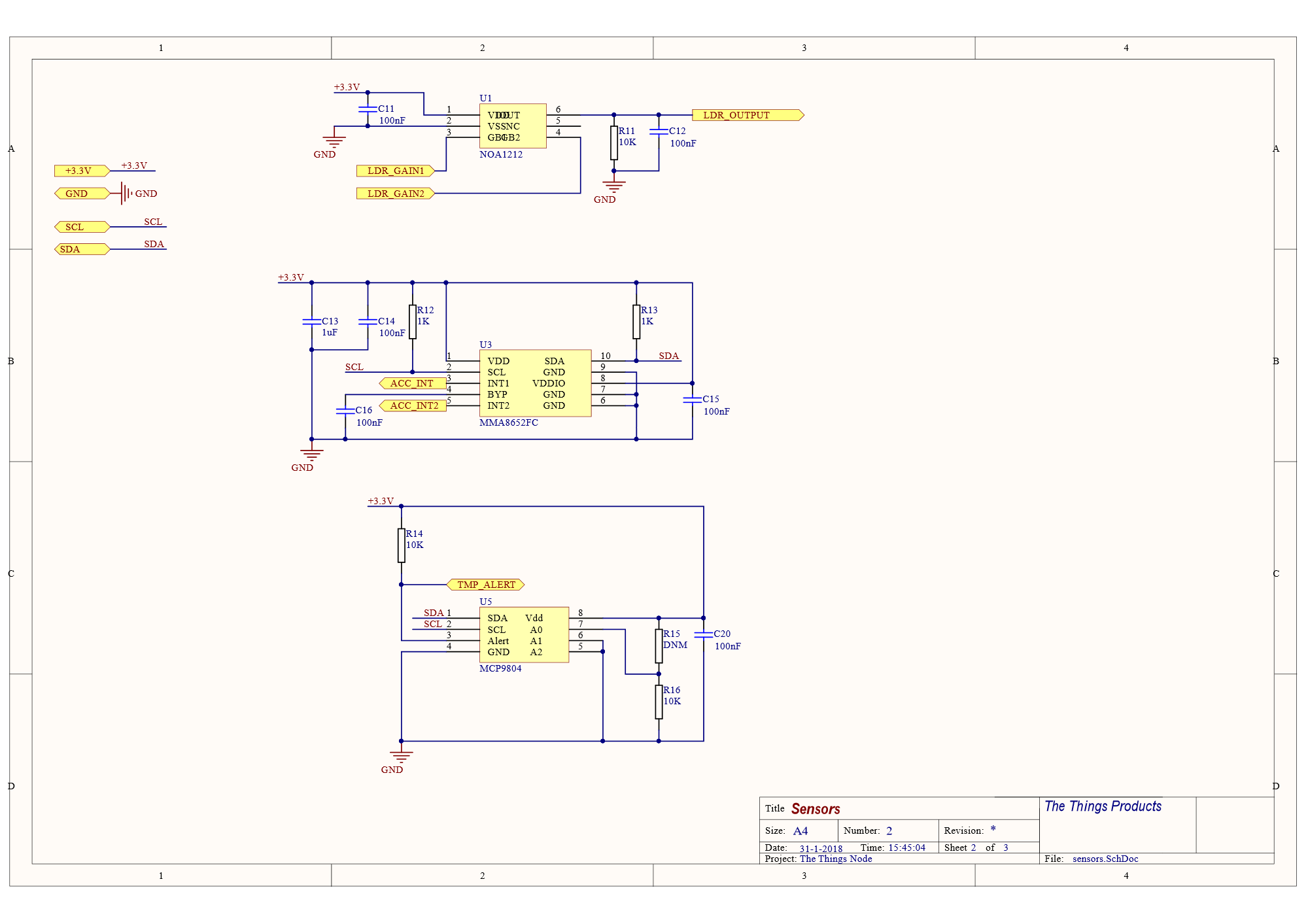
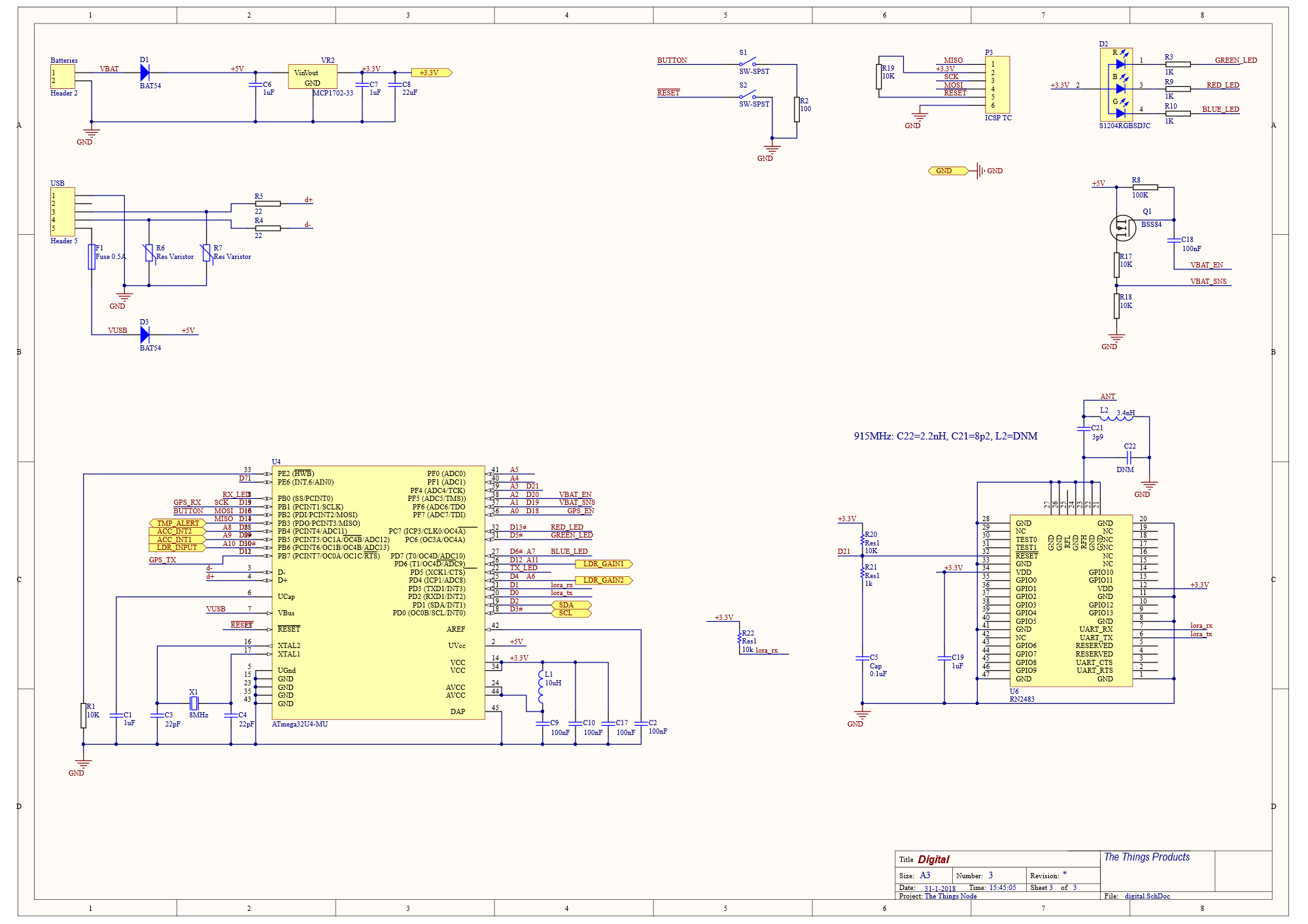
Sure, 3 batteries 1.5V= 4.5V and reading Vbat with TTN library API and fresh batteries indicate 4.5V also, so yes I think there is an onboard regulator, which is absolutely not a friend of low power ![]()
We just need to wait for schematics to hack this (they will come, it’s open source and confirmed by ttn team), but since node are now real could be fine to have at least schematics released ![]()
From the code, it sure does all the sleeping portion including proper detaching from the USB port. As @Charles pointed out, definitely there’s an on-board regulator to step down from 4.5V to 3.3V. Also could be other smaller details like unused floating pins. The battery monitoring circuitry also scales down from 4.5V maximum down to below 3.3V power rail which probably uses a simple resistor divider network (I could be wrong on this guess) and if the resistor values are not selected correctly, it will easily consume mA range.
So, we shall wait for the schematic I guess. @Charles is probably right because most more common regulator usually consumes more quiescent current.
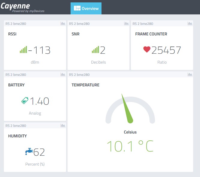
day 88 of the RocketScream single AA battery LoRaWAN temp sensor.
still going strong !
25457 x 5 min / 60 min / 24 uur = days
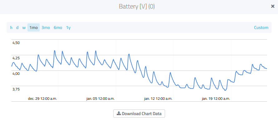
One of my sensors is running on 3 AA batteries and a solar cell. temperature and battery voltage are sent to Cayenne. Great to see the the charge of the battery change over time:
Did you post that somewhere here in the forum or elsewhere on the internet? I’d like to have a look. 
Is the sensor board running at 3.3v? how is the battery voltage being taken
The sensor board is directly connected to the 3 AA batteries and running on variable voltage. The solar cell is direct on the 3 AA batteries. Not very elegant.
These are 1.2V NiMH rechargeable batteries right? If yes, 3 of them in series will stay around 3.6V for most of the time!
That is correct
try this one  (tried it… works ok)
or for an 18650/solarpanel this one
or for a bigger solarpanel/battery this one
Basically this states that the package was delivered using a shipping company that resides in the EU but was sent from outside the EU. It is put on as a reminder that VAT and import fees are still applicable.