I forgot to mention this one, uses the same processor.
The Arduino MKR WAN 1300
I went to the shopping mall to buy some glue… and came back with a pir home alarmsystem with 2 remote controls for 8 euro
is there room for an arduino+rn2483 ??? … lets take it apart
there’s not alot of room inside, but he the thing works for the price of an empty enclosure.
interesting is that it uses the same chip BS00001 as all the other china PIR’s
If you take out the electronics there is room for your own pir loralarm … thing is not waterproof
maybe a TINY LoRa inside so you can still make use of the remotes leaving the original pcb ?
Lol, what’s inside? I wonder… Didn’t we al start “fixing” tv’s or radios like that?
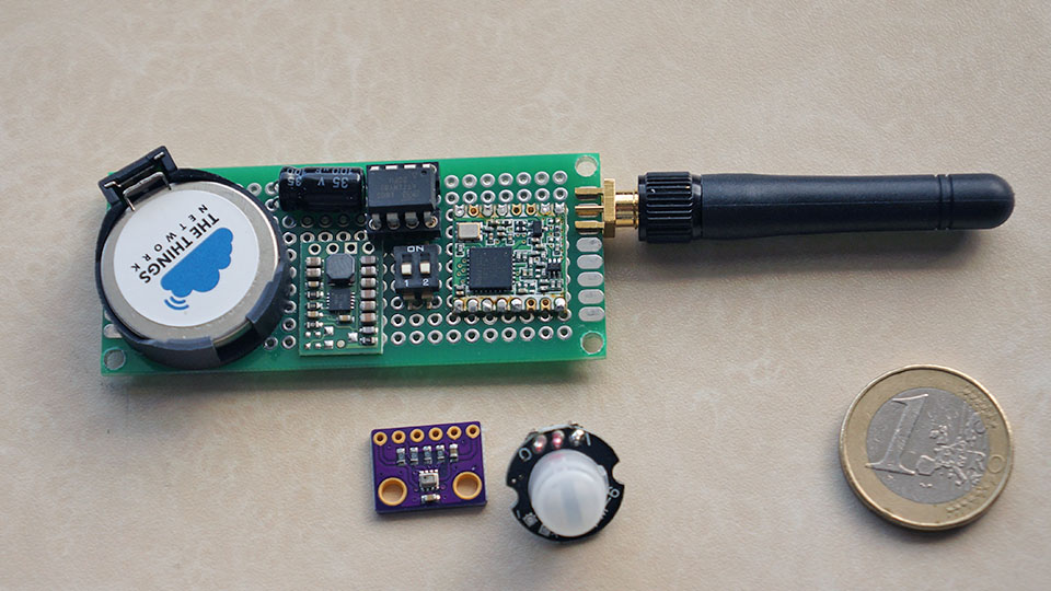
3v3 ‘power’ unit with LIR 2450 - its also very easy to make your own charger for this type of LI-ION battery.
when charged connect it to this dc/dc converter which gives you a constant 3v3 output for your mini node
when I remember correctly, that one has no undervoltage protection …
true … now I think about it, there’s a problem because I wanted to read the operating voltage internally but that’s stupid , its always 3v3 because of the dc/dc board.
my idea was to free a pin, like mentioned in the 85 topic, and use that for a PIR so I can switch the use case : PIR or TEMP
have to think a bit now because you may drain these coin cells to ca 3v, drain more and you damage them.
so we have no pins left …how to detect ?
and why not using the attiny167 board?
some more pins but not much larger?
removing the 3V3 regulator and the pwr led it shout not draw much current.
yes sure… I can build it with any processor or RF module, but I was inspired by the ATtiny85 topic and I looked and found everything in my workplace that I thought I need to ’ quickly ’ build a small node…
btw the board you mentioned needs a levelshifter with the rfm95
- maybe found a solution … a separate little protection board between the LIR2450 and DC/DC converter
this one has a 2.75V cutoff but maybe you can tweak that a bit by changing a resistor
- update small lithium protection boards arrived… have to test the cut off voltage first
yes that’s the same idea, but be carefull, these little protection boards are specific designed for 18650 batteries and they have different characteristics then that LIR2450
I tested a few in the past … if they say 'cutoff voltage = 2.75v ’ don’t believe them … test it first and don’t be amazed when the protection kicks in @ 2.35v ’ … or never
finally … The REAL DEAL ! thank you
Good to see that stuff finally starts arriving. Enjoy it
Leonardo Pro Micro ATmega32U4 8MHz 3.3V !
so direct connection to RFM95 / RN2483 possible ? a mini TTN node ?
always run BLINK to check module
- identifying individual components (click for BIG)
after loading the passthrough sketch in the TTN node
I started this ESPlorer V2… nice free tool for the ESP8266 and now extended with preprogarammed buttons for the RN2483
to start just double click ESPlorer.jar
tool seems to work
testing TTN node with RN2483 firmware 1.0.1
loaded with the basic sketch
Rx = 3.8 mA
Tx = 14.5 mA
first conclusion … don’t leave the basic sketch in the node with the batteries
I will have a closer look at the ‘sleeping’ code … and ask @Charles and @rocketscream , the low power specialists, for advice how (and if possible) to improve this TTN device
now I will upgrade the RN2483 firmware and test again :
ok firmware updated to 1.0.3 with the passtrough sketch and the semtech tool
- that was a bit disappointing… with the same basic sketch but with the updated firmware no difference, continue
fits without tweaking
The idea is to make an simple (work) table stand for testing different antenna’s and to make it portable.
I found on eBAY this Studio Photography Light Flash Stand Support Tripod and this Studio Lamp Boom Arm Reflector Single Swiveling Grip Head Bracket Clamp Holder
nice antenna.
a recommendation?
any measurements?
it looks like it actually sends the sleep command to the RN module, and also triggers the function to put the uC in sleep mode. But I also can’t get it below 3.x mAh, even with bare minimum code. Maybe there’s a HW voltage regulator drawing the remaining current?
we need the schematic…
everything is published now https://github.com/TheThingsProducts/node/tree/master/hardware