yes - its not suprising to think things that way.
However, the maths say that a 6dBi antenna will only give a 50% increase in distance when compared to a cheap dipole (e.g. from 300 m to 450m) if the antennae are used in the same place
Thus, on a 14 dBm limitation, you can’t have better than an antenna of 0 dBi if you’re transmitting power is already 14 dBm ?
In Eu I believe the 14db limit is set allowing for the use of a 2dbi ant (2.15dbi?), and if you have a feeder cable, pig-tails and connectors that induce some loss then you can compensate with better ant (1db of connector/adapter and (ultra)low loss, say 2-3m of RG58 or 5-10m of Aircell5/7 or LR-400, between GW connector and ant would allow for a 3db ant. Hopefully someone will shout if I’m wrong on this one… 
Correct, but please see slight adjustments below - to try and make this tricky thing clear.
-
Thus, on a 14 dBm (ERP) limitation, you can’t have better than an antenna of 2.15 dBi if you’re transmitting power is already 14 dBm (ERP) (N.B. its often rounded down to 2dBi for easy calcs)
-
Thus, on a 14 dBm (ERP) limitation, you can’t have better than an antenna of 0 dBd if you’re transmitting power is already 14 dBm (ERP)
N.B. The ERP specification means that the power limit is expressed when using a dipole antenna.
N.B. A dipole antenna can be expressed as having 0 dBd gain or 2.15 dBi gain.
and as Jeff says, you can mitigate all this by adjusting for all the inevitable losses that occur (e.g. in the connectors and cable). Because of these losses, you can legally use an antenna of higher gain.
This is how you can calculate it.
e.g.
    output power limit        = + 14 dBm (erp)
    loss in SMA connector     = -  1 dB
    loss in cable             = -  2 dB  (for 20 metres @ loss of 1db per 10 metres )
    loss in antenna connector = -  1 dB
    Antenna gain              = +  4 dBd (antenna is advertised as 6dBi)
If you go through the calculation above, you see that the predicted power output from the antenna will still fit within the specified power limit because the losses match the antenna “gain”.
i.e. Even if an antenna with gain of 6dBi is used with RF power at the limit of 14dBm, the resultant field strength radiated by the antenna will still be within the limit.
Remember also, that the antenna is focussing the radiation and that the field strength is measured in the direction which gives the maximum strength.
For the calculation above, I used arbitrary dB figures for the connector and cable losses (e.g. 1dB per 10 metres). If you want more accurate “dB loss” values, you need to look up the spec sheets and check what the loss figures are for the frequency used e.g. 868Mhz
e.g. Have a look at this pdf link for a cable spec (check your downloads folder) which seems to suggest a dB loss value of about 1.5dB per 10m (i.e. 15dB per 100m)
https://www.google.com/url?sa=t&rct=j&q=&esrc=s&source=web&cd=1&ved=2ahUKEwi_8ZTP5P3cAhVOiRoKHfXKBJ0QFjAAegQIABAC&url=https%3A%2F%2Fwww.pasternack.com%2Fimages%2FProductPDF%2FRG400-U.pdf&usg=AOvVaw2F2LkOUIJW6NOrdeoaI20Y
Look for the “Electrical specifications by frequency”. What you see is that the cable loss value per metre is dependant on the frequency used - it increases with higher frequency.
Obviously for Europe and USA, we are looking for what the value would be at arround 900MHz).
If you have the correct specification sheet for the cable and the connectors you are using, and you know the antenna gain value (dBi or dBd), you should now be able to put it all together to calculate the dBm figures that would be output (by your antenna) at different lengths of cable.
Alternatively, you can use this on-line calculator
There are other considerations, but you can usually ignore them as long as you have a well matched antenna (50 ohm) and you are using a cable with the same “Characteristic Impedance” (50 ohm again),
The main thing to take away, is that antenna manufacturers always quote dBi figures - which is naughty really because power limits are almost always specified with ERP (and not EIRP).
What this means is that you have to “downgrade” the gain value to the correct figure by subtracting 2.15 dB from the dBi figure that the antenna manufacturer quotes.
Its no wonder that antenna manufacturers are quite happy for buyers to mistakingly believe that the more expensive the antennae, the more “magic smoke” the antenna has, and also the continued use of dBI to make their gain seem better (which just misleads the unwary ![]() )
)
The other takeaway is that distance gain is proportional to the square root of antenna gain
What this means is that it is realistically impossible to get an horizonally omnidirectional antenna with a reasonably focussed vertical radiation pattern (suitable for Lorawan) that achieves a distance gain greater than 4 times over a dipole positioned in the same place
Appologies for repeating the same thing
I would put the loss in connctors at around 0.1dB per connector. Certainly when I add combinations of extra SMA or BNC connectors in the chain those are the losses I actually measure and a bit less fo NType.
Then there is the LMIC library, which appears to setup the LoRa device for 16dBm when 14dBm was intendended.
Not sure if its in order to share this on this thread but this is about antennas.
I was reading this article on “Antenna Basic Concepts” and came across the “5/8 over 5/8 over 1/2” collinear antenna design. I wonder if anyone has tried this for LoRa frequencies.
I did try out the design for an 868MHz collinear antenna, using core from an RG-6 coaxial cable. The lowest section was roughly 172mm, while the upper sections were roughly 215mm each. I say roughly because I wasn’t taking very precise measurements. The loops in between sections had a 30mm diameter.
I tested this by replacing an existing quarter wavelength antenna with new contraption (not having a VSWR meter this seemed a reasonable first test.). Surprisingly, I notice roughly 11dbm improvement on signals received from a gateway I have installed between this antenna on a node and a quarter wavelength antenna on same node. This difference was maintained consistently with two similar nodes, one having this antenna and the other using a quarter wavelength antenna. I also notice same difference between this and other 868MHz antennas I have, all quarter wavelength.
I haven’t tested this for range but will do so in the coming days.
Has someone tried this design and can the person share the experience?
I have tried similar designs with mixed success. Small amounts of gain, 3dBm perhaps, but in one case although the antenna was built, tuned accuratly and had a very low SWR, it was actually a worse radiator than a simple 1/4wave.
If an antenna was a real 11dBm improvement over a standard 1/4 wave it would mean that a standard node was transmitting at 25dBm, whereas the legal limit is usually 14dBm.
The antenna will be installed with a gateway. In view of your statement above, will it be breaking any limits?
If the gateway transmits or downlinks data to nodes then yes you would be breaking the allowed ERP limit.
And setting antenna gain or Max Tx Power in the gateway config files should fix this? Yes?
My knowledge of antennas is almost zero, but I would like to enhance at least a bit the functioning of my gateway. Thus. I built a rough version of the GPA described in this story, and tried it outdoors. It is for a Dragino RPi single channel gateway.
I started from an 86mm driver and today I cut a couple of pieces, to shorten it according to instructions). After each cut, I checked RSSI and SNR of 3 nodes sending to it (likely placed too close). I found slight enhancements. Then I went out with two of them for a run (literally), and compared to a run made a couple of days ago with the 86mm version (though placed higher, I will go again in a couple of days with identical setup).
It seems that now RSSI is slightly worst, but SNR is better. E.g., at 800m almost line of sight, 86mm version was -11,-13; 80mm version is -122,-3. Something similar in other close geographical points.
Sum seems similar. I do not have yet a clear idea on the combination of those numbers, but simply put, shall I be worried about lesser RSSI or glad for better SNR?  thanks.
I bought a big outdoor antenna but I am unsure of how I am supposed to mount it. I need to choose a mast but I am unsure of where to buy the equipment to mast it. It’s an outdoor antenna with an N-Type socket. It is a but less than an inch in diameter.
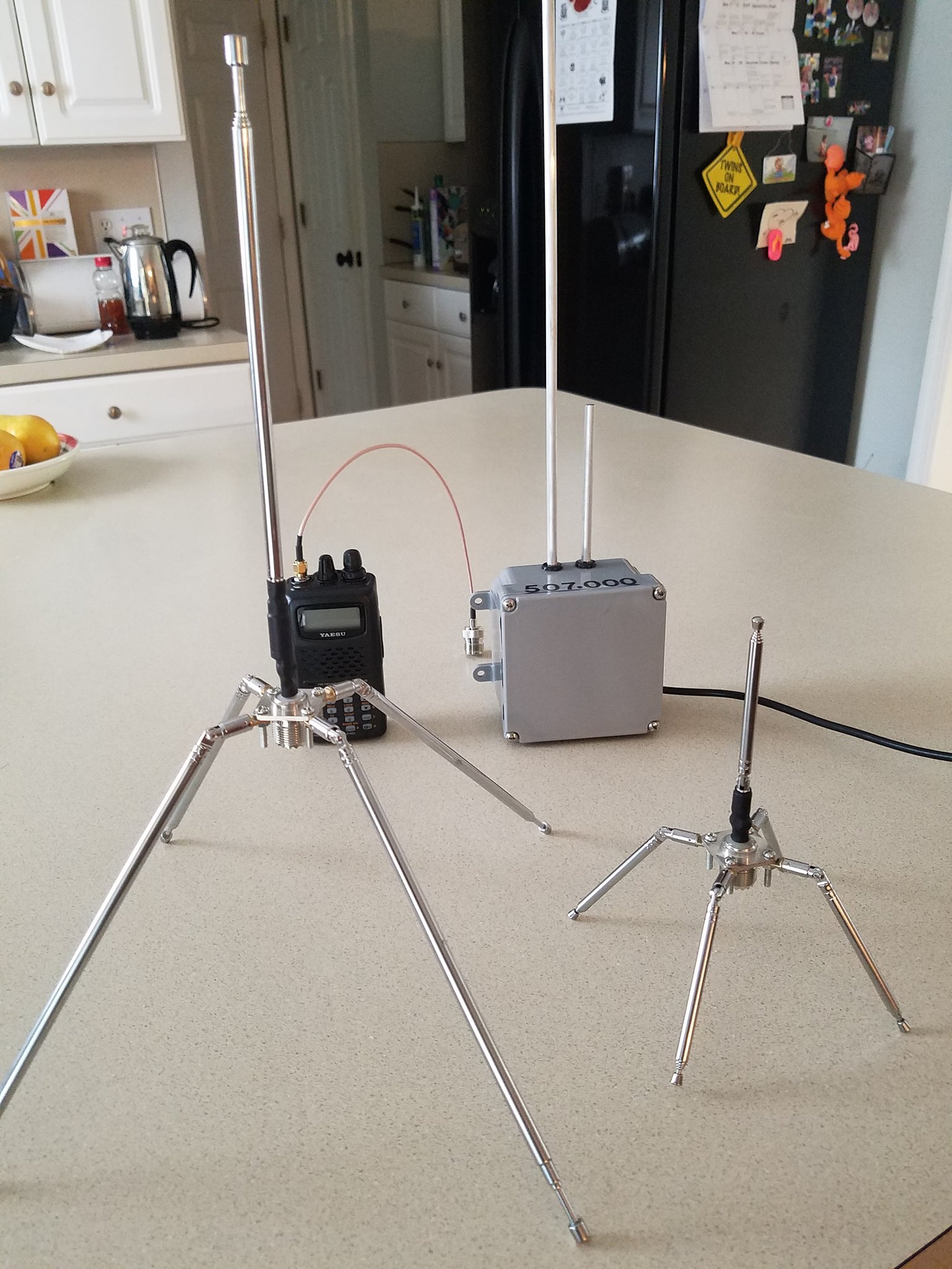
They look about ready for a landing on a planet somewhere.
they are very easy to ‘tune’ …
I don’t know where you are based so I can’t make any specific recommendations.
Search online for “telecom pole” and “telecom mast” to select a mast of the correct diameter and length.
Search online for “T&K brackets” to fix the pole or mast to a wall.
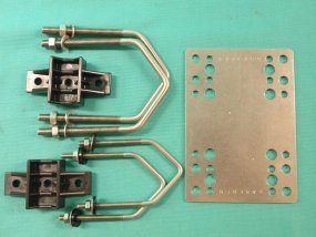
Search online for “telecom mast clamp” to buy hardware like the picture below to fix the antenna to the pole or mast. The 2 grooves in the base of your antenna are for the U-bolts of the telecom mast clamp.

Did someone try this one? It is presented in a slightly confusing way, however is 39cm long.
Thanks BoRRoz, it is kind of you to refer my article
I actually use these specific antennas on a whole load of gateways, including outside ones (although I use heatshrink and amalgamating to seal them). They have worked fine outside for over two years with no deterioration.
