Pitty. Especialy downtilt antennas like this one can nicely be simulated in propagation simulation tools.
I’ll be patient.
The downtilt only occurs in frequencies used by the 915MHz band, at the “lower frequencies” around 870MHz the main lobe is horizontal. Could make a comment that we who use 915MHz have got an advantage for once.  But wouldn’t do such a thing.
Since I can’t transmit in the 868MHz band (its a mobile network down here), I could not test it.
That is a good comment. Tilting will alter over the used frequency. It seems as if this antenna was designed primary for 868 where the tilting at 915 is a side effect.
question for the specialists
I need/want a LoRa 868 antenna that is directional in 4 directions that can be used mobile.
So I was thinking of something like this, on a pcb that I can hide in a big tube slice.
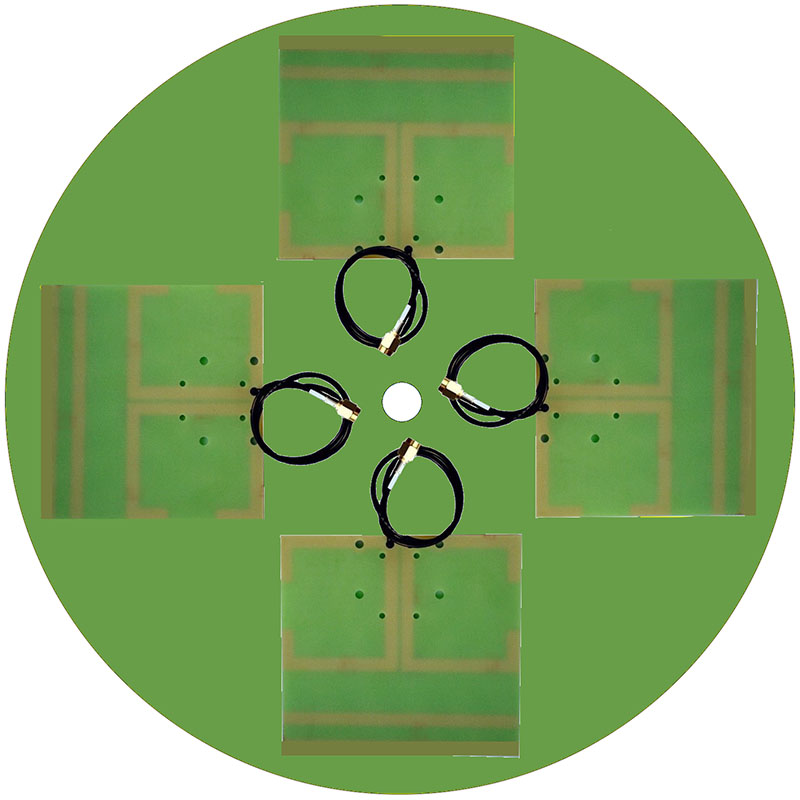
could something like this work ?
mmm… why not omnidirectional at this point?
because I need directional 
its for a fully automatic ‘track and trace’ system to find nodes / gateways - that idea lives in my head @ this moment 
Maybe take a bit of inspiration from ADF in aircraft. It uses a loop antenna (raamantenne) combined with an omni to form a cardioid reception pattern. They used to rotate but these days that is done electronically.
Great!, I did not know it yet. I have not received any email. #happy
I guess it could work. However you have to take in account that the gain of such small antennes to not have a high front-to-back ratio. Reflections in your surroundings would therfore have more influence. I think the influence would be less if you mount it with free sight on a roof. Why not use one directional antenna and start experimenting by looking at the RF spectrum with a RTL-SDR.
gain is not that important… direction is (and mobillity !)
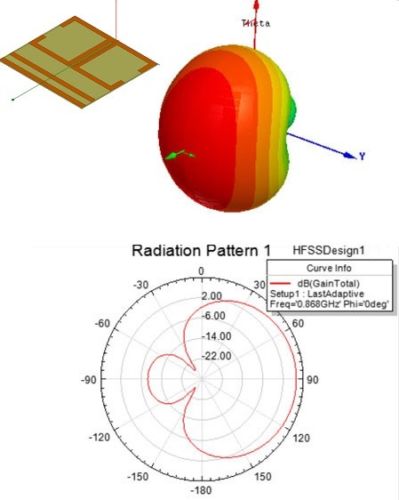
Sorry, my typo. I wanted to say that the gain was relatively low and the front to back ratio poor. I guess if you would want such a setup to hunt for nodes you would benefit more if you would have an antenna like a HB9CV or a biquad antenna with better front-to-back ratio…
I want to build a mobile device So no yagi’s.
Tnx… I guess I will just have to test a few things myself first 
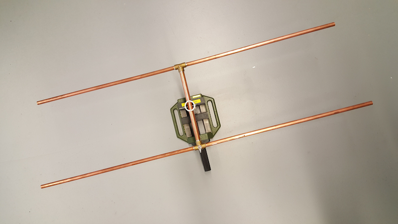
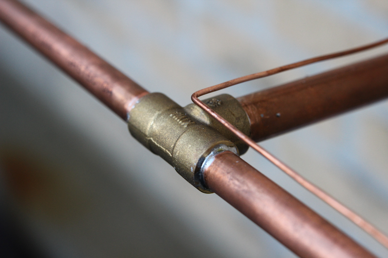

hb9cv 
Hopefully we get our next week and maybe repeat your experimental for the 868 band
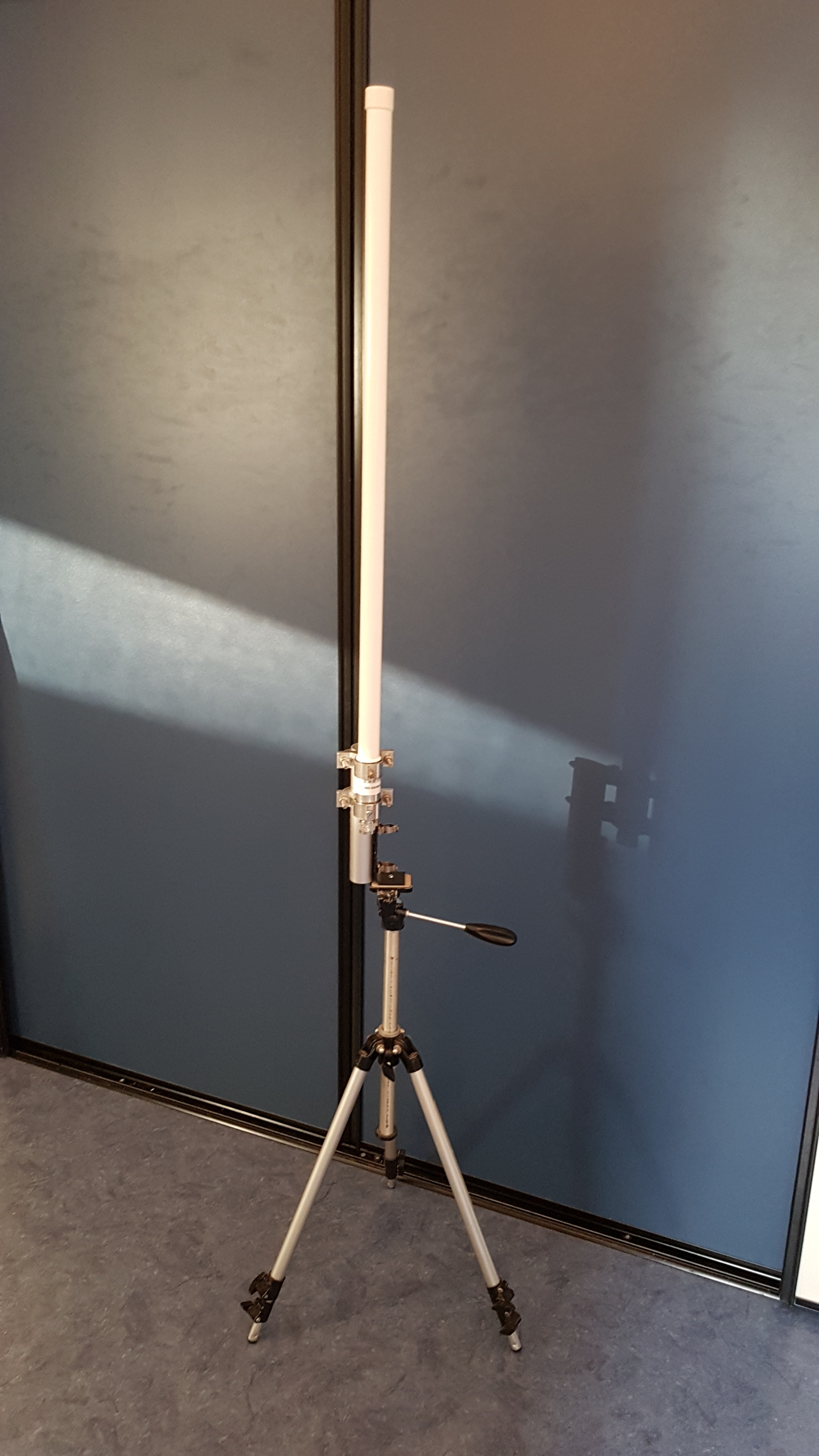
And there he is! Installed on this temporary tripod for coming measurements.
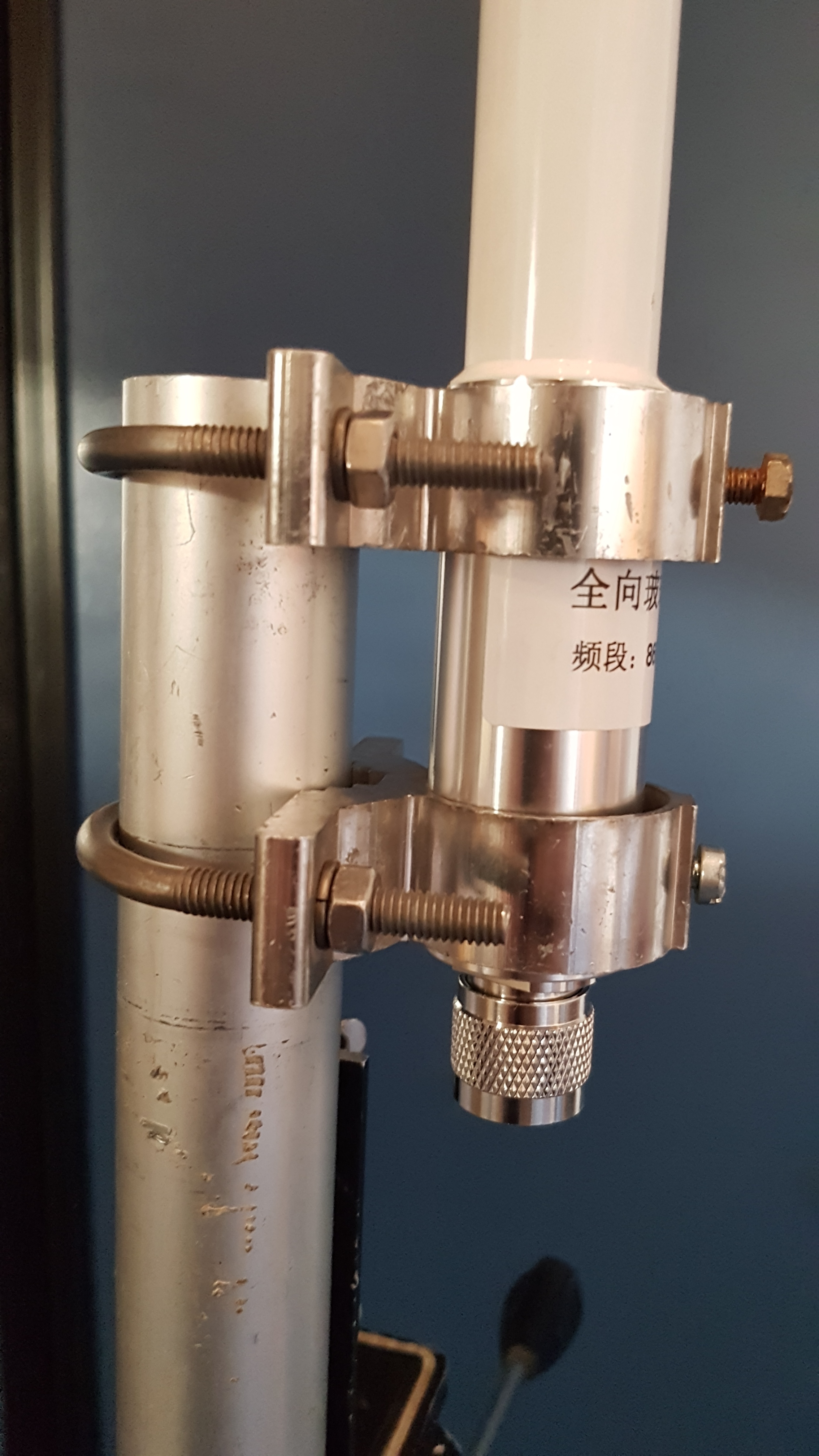
Only problem I had was that I cannot install the antenna proprely with the provided clamps. No idea how RAK thinks it should work. Therefore I used the clamps of an old chineese VHF/UHF antenna.
Love the RAK test reports, all sorts of details inc patterns vs frequency,
Not just the basic meaningless one “gain” value - often made up to appear very high, although like @BoRRoZ said high gains may even be bad if pattern is in the wrong direction…
Can’t wait to test this one.
You raise an interesting point ![]() . With such a wide range of mounting arrangements used on different sites the antenna supplier hasn’t a clue on how the antenna will be installed.
. With such a wide range of mounting arrangements used on different sites the antenna supplier hasn’t a clue on how the antenna will be installed.
For example, its common to mount to a vertical tube but then what’s it’s diameter? It could be a outrigger from a tower and be a horizontal tube (again what size)? Alternatively it could be a bracket secured to a structure like a chimney.
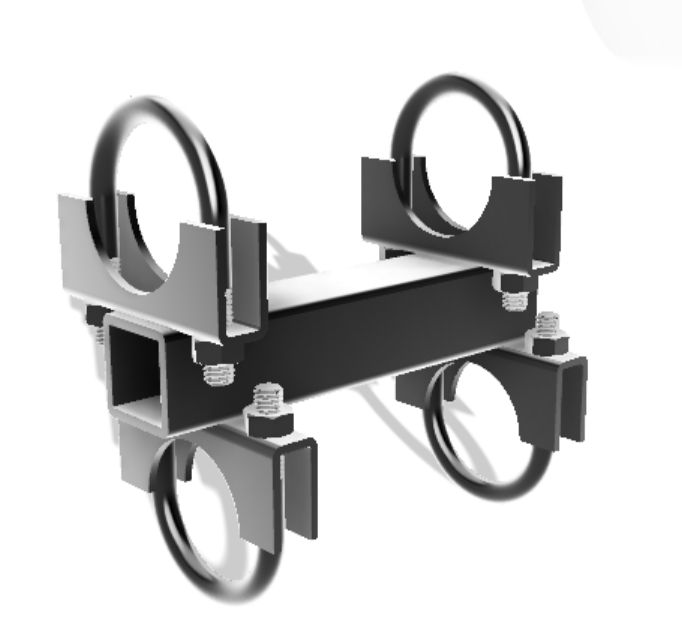
Reflecting on your comment I realised I tossed the clamps that arrived with my antenna on a pile of similar bits and pieces as I build my own clamps. I prefer either stainless steel hardware or Hot Dip Galvanised bolts, nuts and clamps rather than the electroplated versions which rust very quickly. (Example The BIG and SMALL ANTENNA topic part 1 - #451 by BoRRoZ ) I can get a range of clamps sizes from car exhaust suppliers and fabricate from there.
I wonder if there is an opportunity to design and sell a set of universal antenna clamps for Lora systems?
this design is used on boats
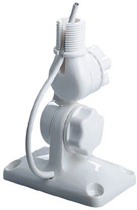
this (dutch) webshop has a lot of material
I contacted RAK for radiation patterns and got als the document as linked to by @jmarcelino. In this document I found the intended mounting for the antenna and the brackets. I have reproduced this mounting using “aluminum corner profile” (not sure about the translation from “aluminium hoekprofiel”).
It works but I have observed potentional stability issues. It could result in metal fatigue of the aluminium pice.
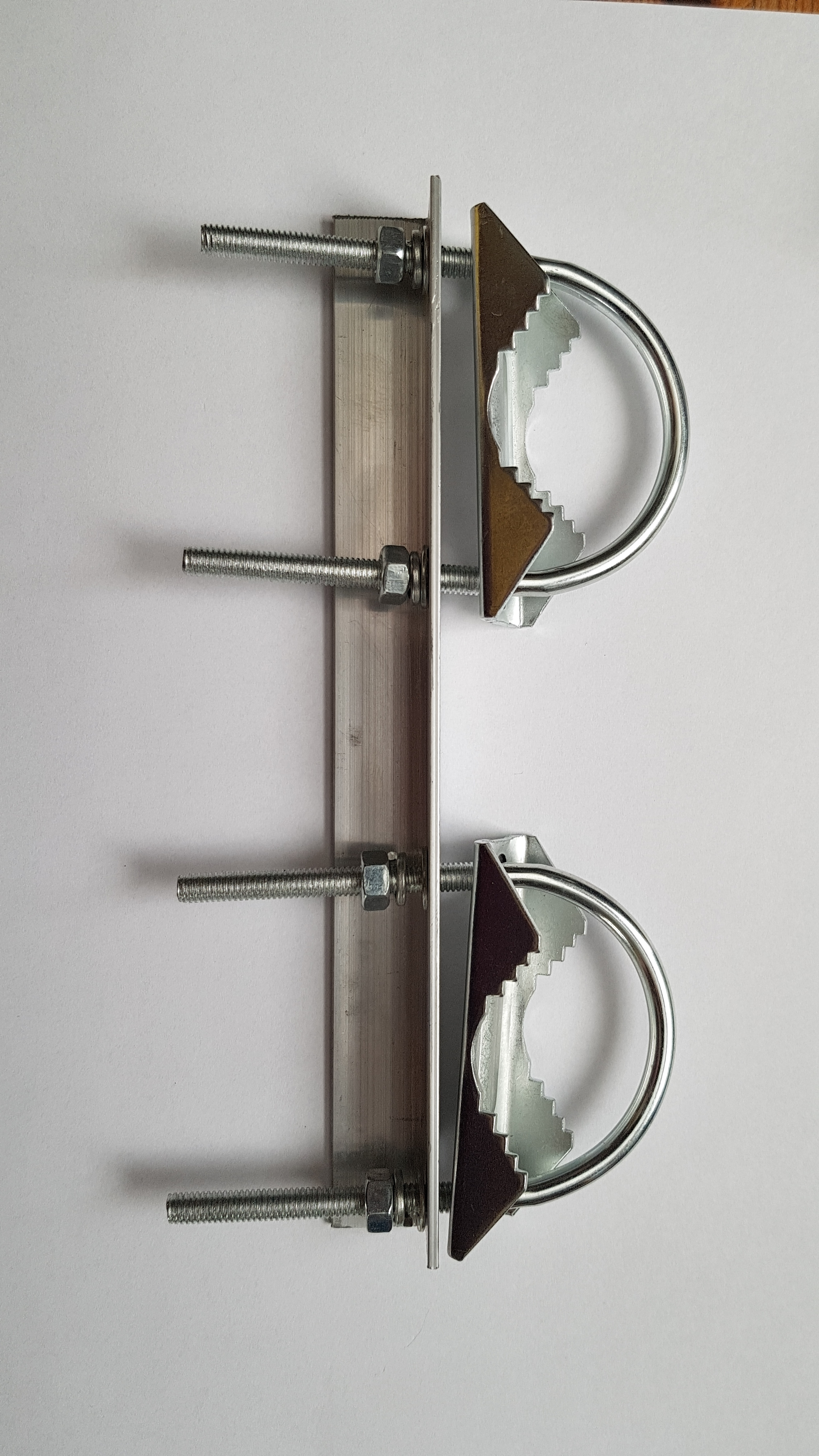
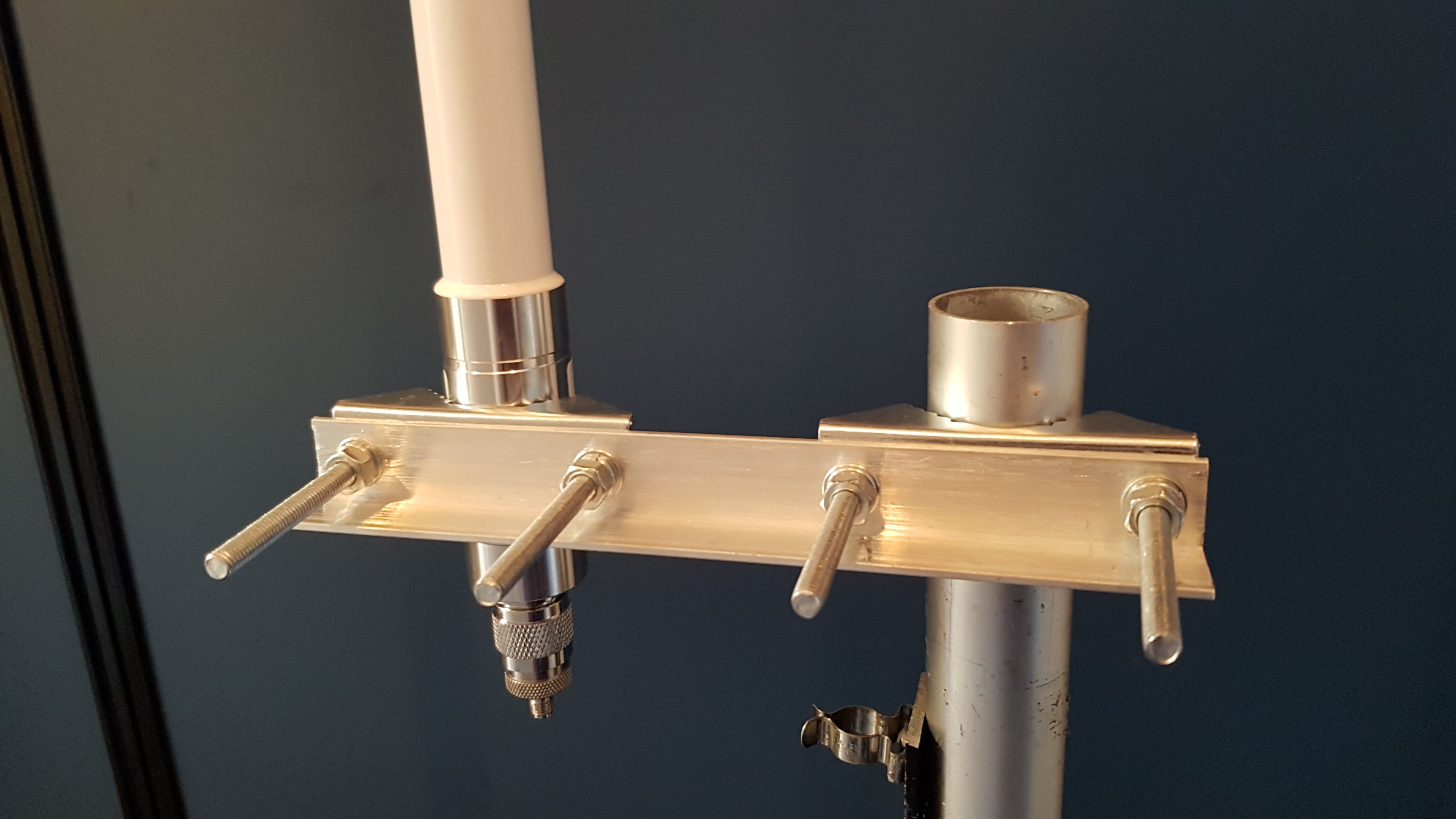
I normally try to keep the antenna and support pole as close as possible. This is the type of clamp system I often fabricate. By selecting clamp sizes to suit, the same design works on almost any size pole and any size antenna.
I know there are better designs but it’s quick to fabricate.
