And when you see that thin coax cable (mostly RG174), you can easily count 1 dB loss for each meter (@ 868MHz) .
It is not necessarily correct to say a pure isotropic antenna would be better for a mobile node, for two reasons:
1/ 1km away from your antenna, the ‘narrow’ cone of your radiation pattern will be hundred of meters wide, so you wouldn’t have any issues hitting a gateway
2/ Closer to your antenna, there would be radio blind spots. Most of them are above or bellow it, so in most circumstances they matter precisely squat. It does matter, however, when you are close enough to a gateway you somehow ended in its shadow area. Thankfully, it’s not the end of the world, because the indirect path capabilities of LoRa are pretty impressive, and you would probably get a decent signal reflected from somewhere.
Another note: isotropic antennas and 1:1 VSWR are impossible in real life, they’re just used as handy points of references.
This is the best document I found so far for understanding antennas and their specifications:
Gig,
- These lobes (or cone as you describe) will remain the same angle, regardless of distance. In other words, if your lobe is 36˚ wide and your antenna is in any random direction, you’ll have 10% chance this lobe hits your gateway.
- These antenna blind spots are due to a non-isotropic radiation pattern. That’s why an isotropic pattern is best if your antenna is mobile in any direction.
And agree on your notes, of course ‘ideal components’ doesn’t exist in real life 
I think you misunderstood what I meant.
Let’s assume there’s 36° between the -3dB axis on each side of your lobe, on the vertical plane.
At a distance d, the vertical distance h between those two -3dB axis is still 36°, so h = d*tan(36/2).
Unless I’ve screwed up my calculations as I often do, at 1m, that’s 30cm high. At 100m, it’s 32m, and at 1km it’s 325m. So, unless your target is more than 325m above or below you, at 1km you are ALWAYS in the -3dB lobe.
Conversely, if your objective is to cover a wide area, using an antenna with a lesser gain (relatively to an isotropic antenna) will make you radiate a lot of energy toward the sky and the ground.
To make an analogy with light: many streetlights are big, round globes illuminating equivalently all around them. You could see them as low gain antennas. They also illuminate straight up, which is completely useless, because it’s the ground to want to see. Now, there are also streetlights that are pointed toward the ground - and with the same energy, they will provide more useful illumination than the omnidirectional streetlights.
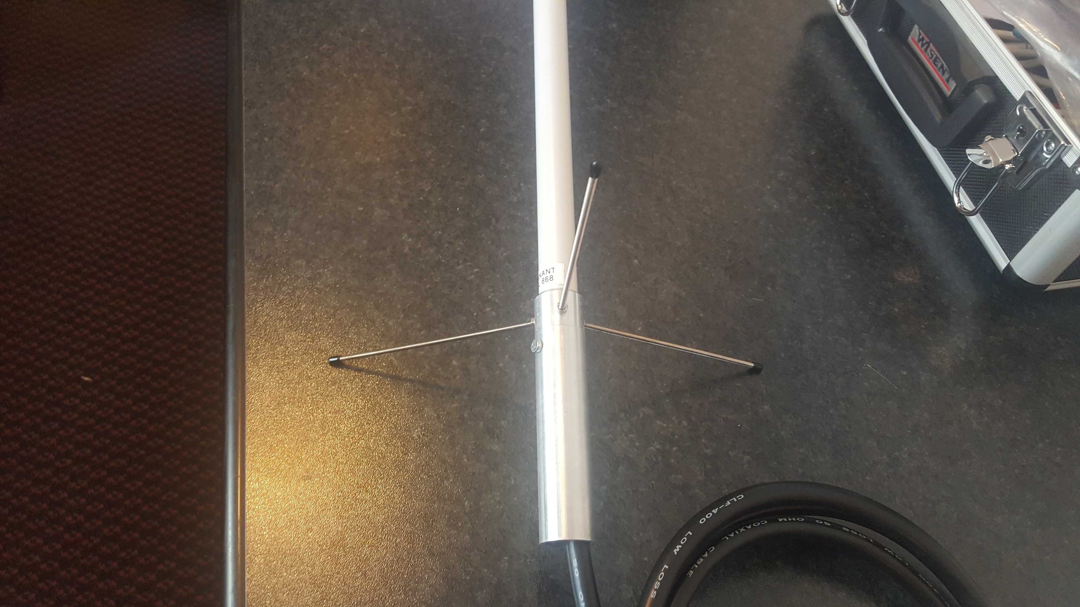
This guy is making his own and selling. Ordered two last week. Will get them tommorow.
interesting ! let us know the results 
I bought the last one listed but I won’t be able to do tests for a couple months. Please keep us in touch with your findings! ![]()
It arrived. Looks really good and professional. Will Try to put it on the roof today. The cable in picture is not included.
Hello,
I have a Cisco LoRaWAN gateway with me here.
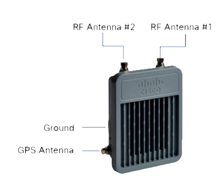
You can attach two antennas to this gateway.
At the moment I only have one antenna for this gateway.
I’m wondering if a second omnidirectional antenna will have a big influence on the reach of the gateway.
Thanks in advance.
This will in most cases drastically lower the reception quality. Two omnidirectional antenna’s both receive the same broadcast from a node, but with a slight phase delay because they are placed some space apart from each other. If you connect these two antenna’s to the same radio, both signals are added and, because of the phase delay, partly cancel each other out.
The (publicly available) Cisco documentation is very brief, but I would suspect that both RF ports lead to the same radio front-end. This is probably for use with high-gain directional antennas.
That Cisco gateway seemingly uses two SX1301. Could it be they have two completely separated radio paths?
Furthermore, they support two separate bands: 868MHz and 915MHz. Maybe they expect the user to use a different antenna for each?
I really wish the datasheet was more complete, or that I had one of those gateways to tear apart.
The SX1301 is a baseband processor, not a radio and it has no RF interface. It communicates to the SX1257 radios through a digital interface.
Indeed, a block diagram and some more information would be handy. I know some people at Cisco, maybe I’ll hear with them  .
.
I know, and this is why it’s weird. Why would you even need two SX1301, if you’re not effectively making two separate concentrators?
I’ll try and get in contact with them through my work, we’ll see if we can get anything out of it.
The Mtech Conduit also has the option of two SX1301’s, afaik to offer dual-band operation with the full amount of demodulators per band.
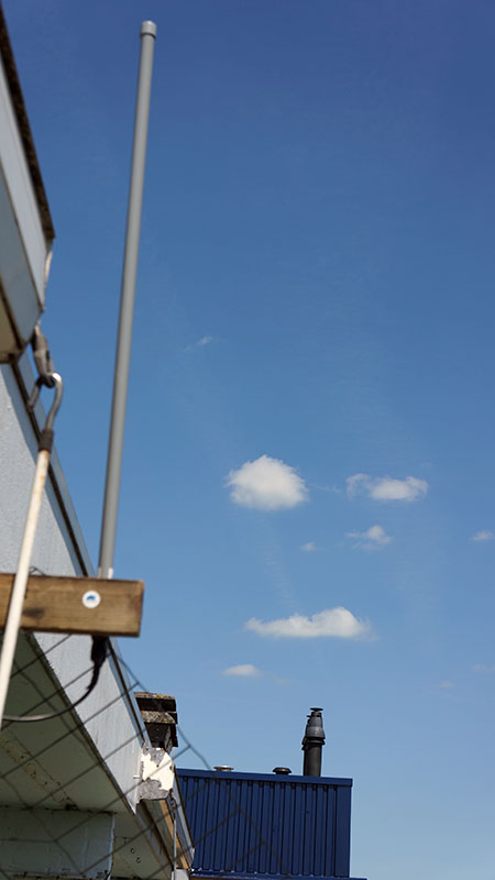
yeah 
A Pitenna instead of a cantenna?
Here’s mine measured using a pocketVNA.
Mine is a 58 cm length with advertised gain of 5 dBi. Bought it from Taobao.
S11 plot is very good and VSWR is close to 1.0 at 868 MHz and 915 MHz. The 915 MHz is shifted a little towards 935 MHz though. On the Smith Chart plot, 50 Ohm impedance is spot on for 868 MHz and slightly at 935 MHz.
I actually bought the 1.2 m length with 10 dBi gain version. But, as I used a forwarding warehouse in China, the warehouse rejected them as the maximum length limit for shipping was 1.2 m and with the box and packaging it was 1.3 m! Had to send them back to the seller. But, seller was nice to do a refund. So ended up with these instead. Got it for RMB90 only and comes with the 2 clamps. The black antenna fixture I bought separately but unfortunately the hole was too small for the antenna to go in, so have to use the supplied clamp instead. The N-type connector to SMA cable was bought from them too at RMB15 for 1 meter length. Basically whatever you guys are paying on Aliexpress, it’s the same amount in Taobao but in RMB. Those guys really make a huge mark up.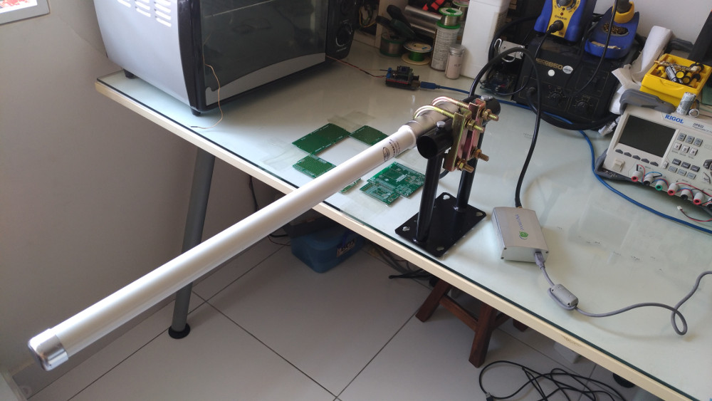
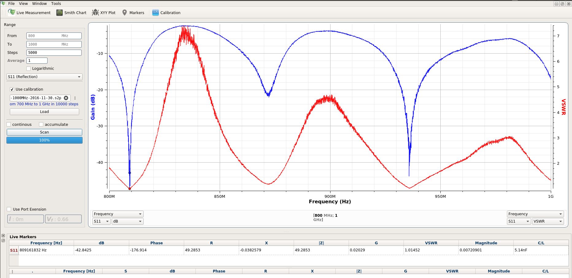
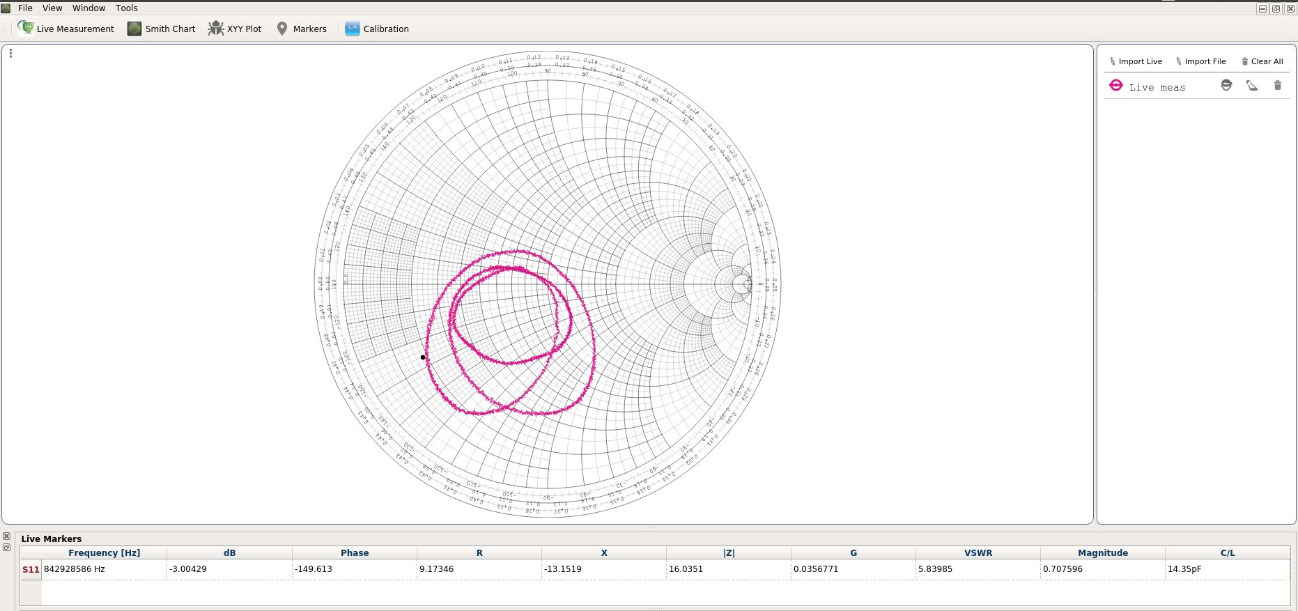
It looks pretty good for 868. It’d be even better if that VSWR were to be bang-on 868MHz, but it’s damn close.
For the Smith abacus, you forgot to put the marker on the right frequency 
Any chance you can get the gain tested? Last time I did something like that, it required two identical antennas and an anechoic chamber, among other things…
If someone had told me a few years ago I’d be looking at RF antenna impedance diagram for fun, I would have thrown them out of the room  .
.