Good to mention the definition for reference. I find it rather difficult for non-professionals without an Open Air Test range (OAT) to reproduce it perfectly. For the average user of this forum, a good indication of the performance of the antenna is very welcome. Therefore I would consider the use of a GP antenna in a antenna substitution measurement to estimate gain.
I value the antenna measured as not bad for that price. I have seen much worse antennas that cost more than this one.
Procom is what we tend to use at work for commercial radio communications installations.
Here’s what I would be interested in:
Given the nice pictures above I think I see gain numbers, I think I see a radiation pattern but I don’t know how to rate the antenna. Is it better than the standard baseline?
The measurement graphs do not show radiation patterns or gain. If you are at the conference tomorrow I can talk you trough.
To value the antenna based on the measurements I conclude: This antenna will likely have more gain compared to a GP antenna and most of the transmit power from a LoRaWAN transmitter in 868 MHz band is emitted by the antenna in to the air.
Hi again @paulb, if you’re going to think about the most “popular antenna” then it’s definitely going to be the antenna that goes at the device or “thing”. The most popular antennae for devices are helical/coil/spring antennae and PCB trace antennae. These are almost always a monopole with a ground plane and are optimised based on physical size constraints and cost. These antennae are very cheap, costing pennies per unit in volume manufacture.
Any kind of “top ten” antenna list should be in 2 parts; the base-station/gateway and the out-station/device/thing.
Is it better than a Taoglas Barracuda OMB 5dB ?
I have not measured that antenna.
From the picture and specifications it seems similar.
I want to point that there is more to an antenna than just RF parameters. An antenna should also be able to withstand weather conditions and environmental influences for 5 to 10 years on a high building.
To my standard both antennas do not meet that requirement. Procom antennas, for example, do meet that standard.
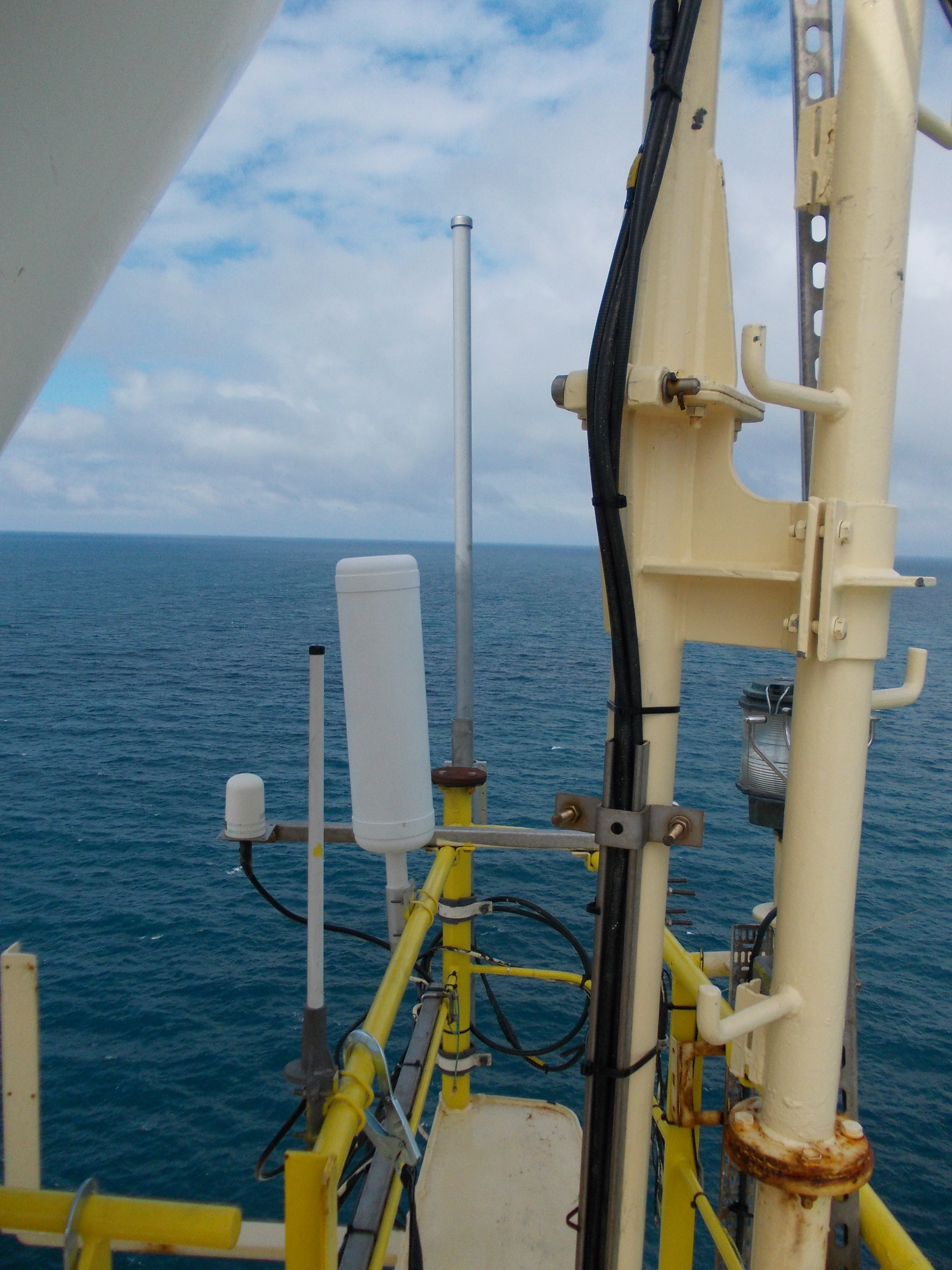
The most common UHF “omni” antennae that I’ve worked with in the hostile marine environment are dipole arrays in fibreglass tubes like Procom, Kathrein and the Taoglas antenna referenced in an earlier post. They are very good but would not meet the requirement in the earlier post for “under a hundred euros”. High quality transmission line is also used, e.g. LMR-400, together with high quality N-type connectors, so the whole assembly gets expensive.
Last week I built this Collinear antenna as published by by @lex_ph2lb .
Here some pictures and practical advice for those who also intend to build this antenna.
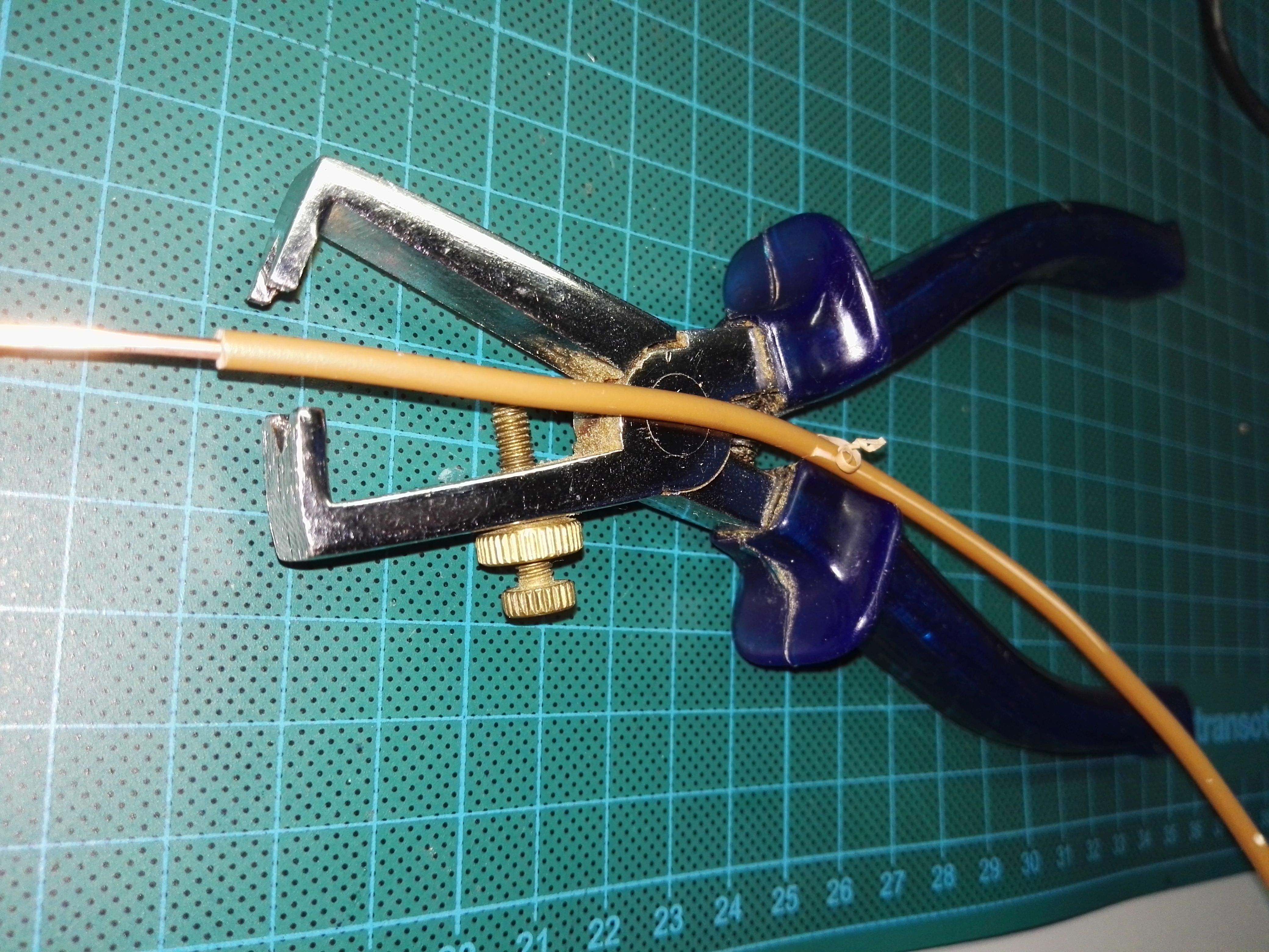
For this antenna I used ordinary 2.5mm² installation cable of which the insulation, with each time a small piece, has been removed.
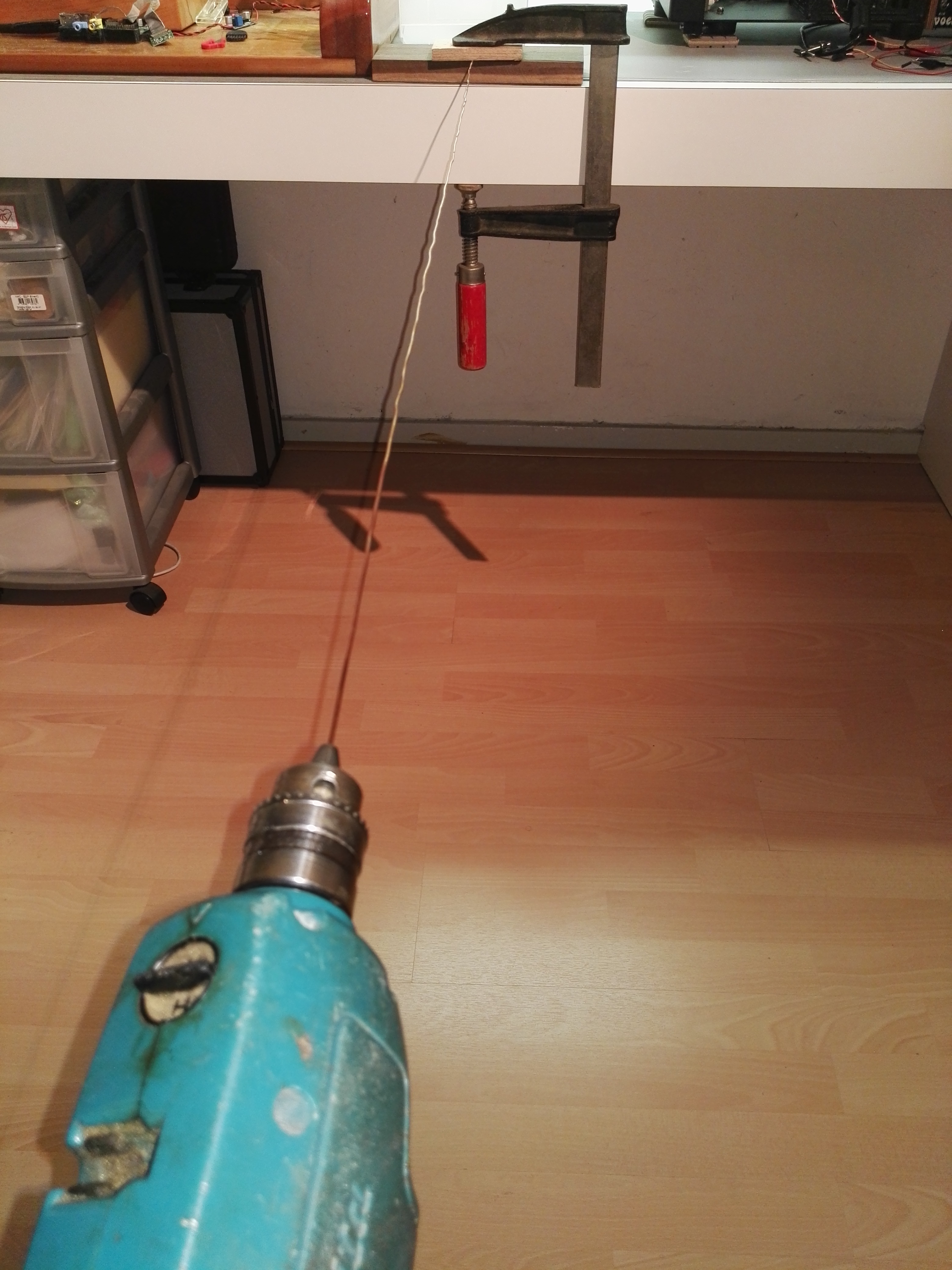
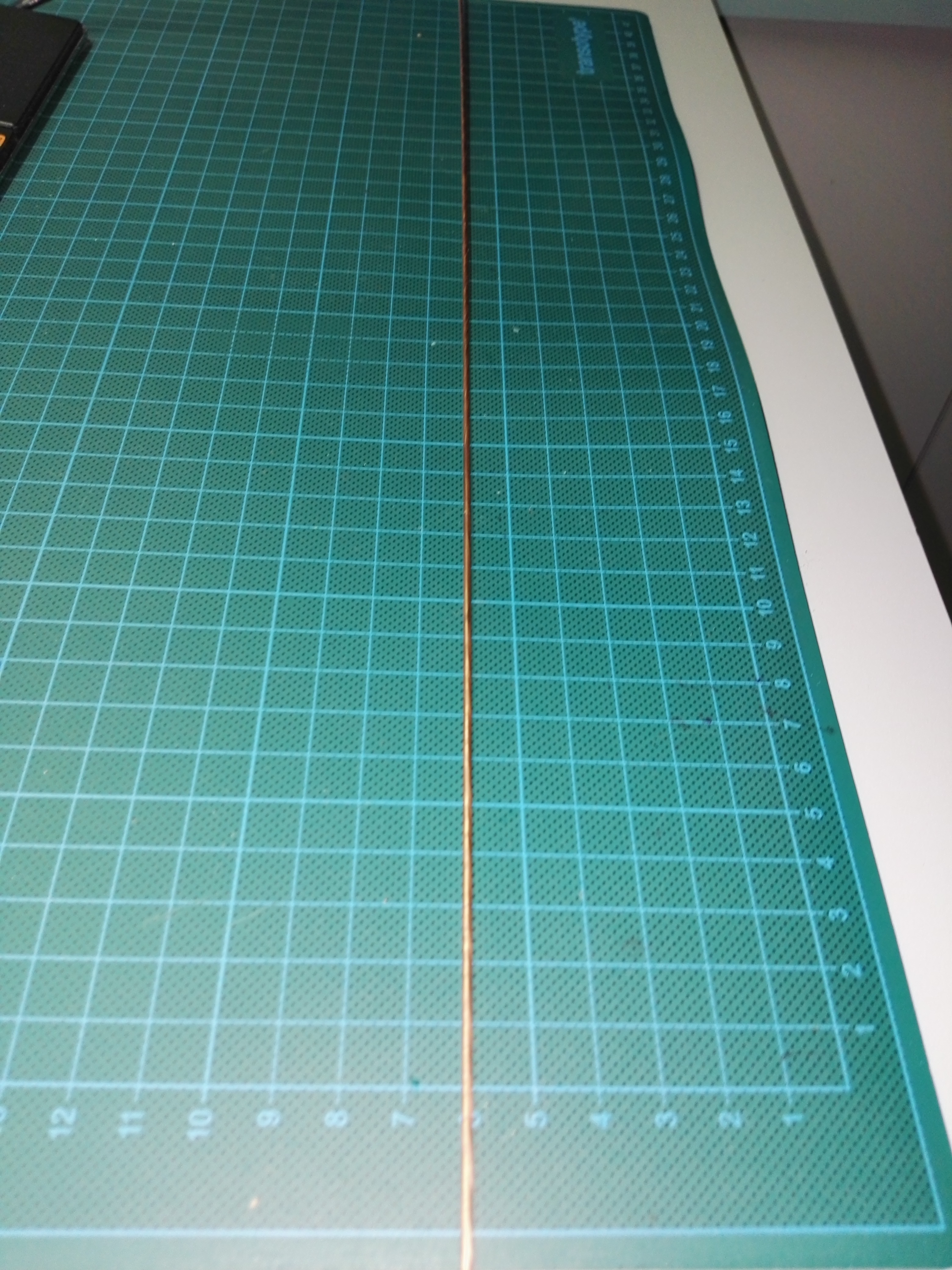
To start with a straight wire I have edited it with a cordless drill; tighten well on both sides and then pull and turn left / right.
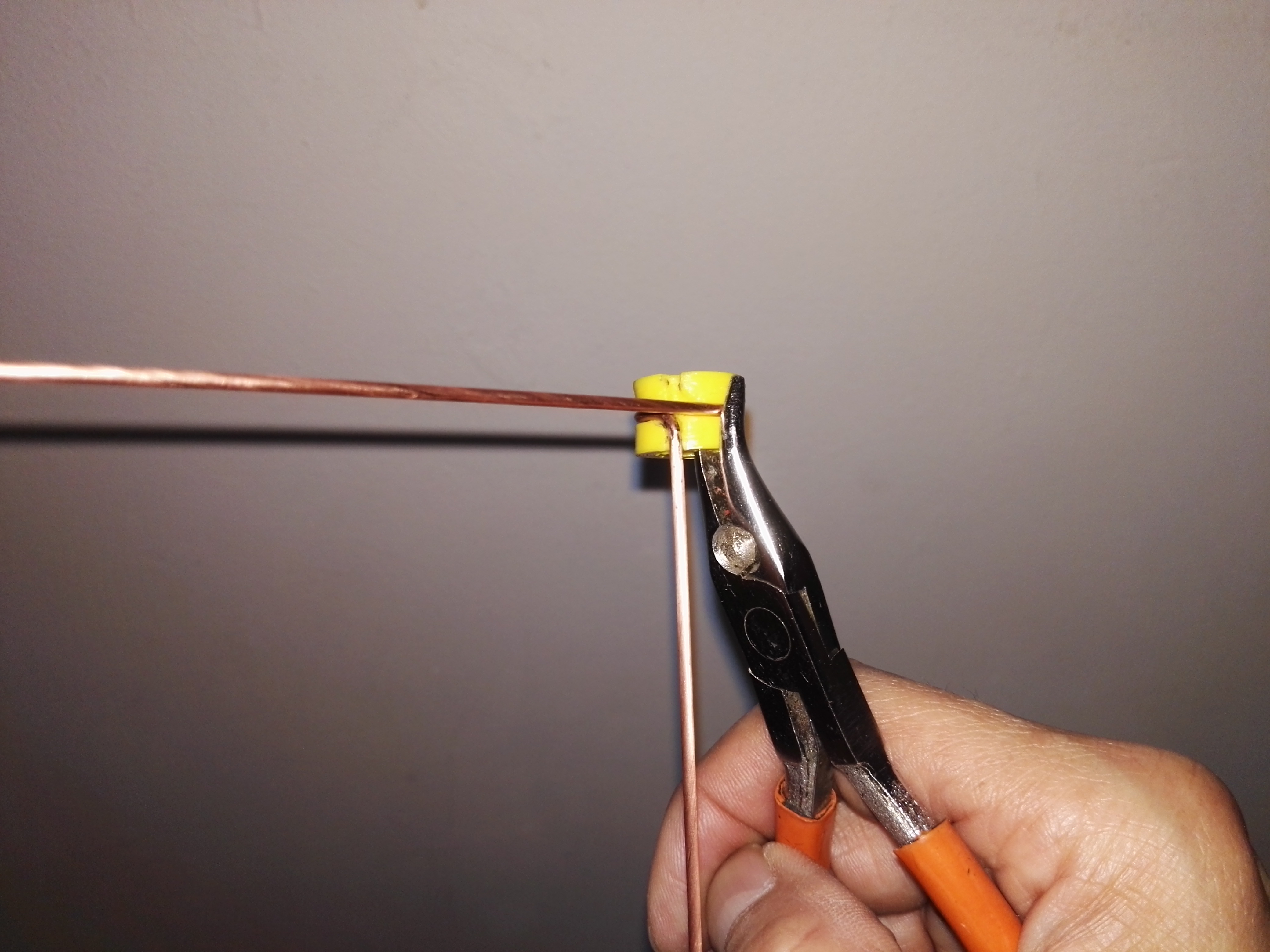
You can bend with this handy tool by Mario Zwiers and pliers
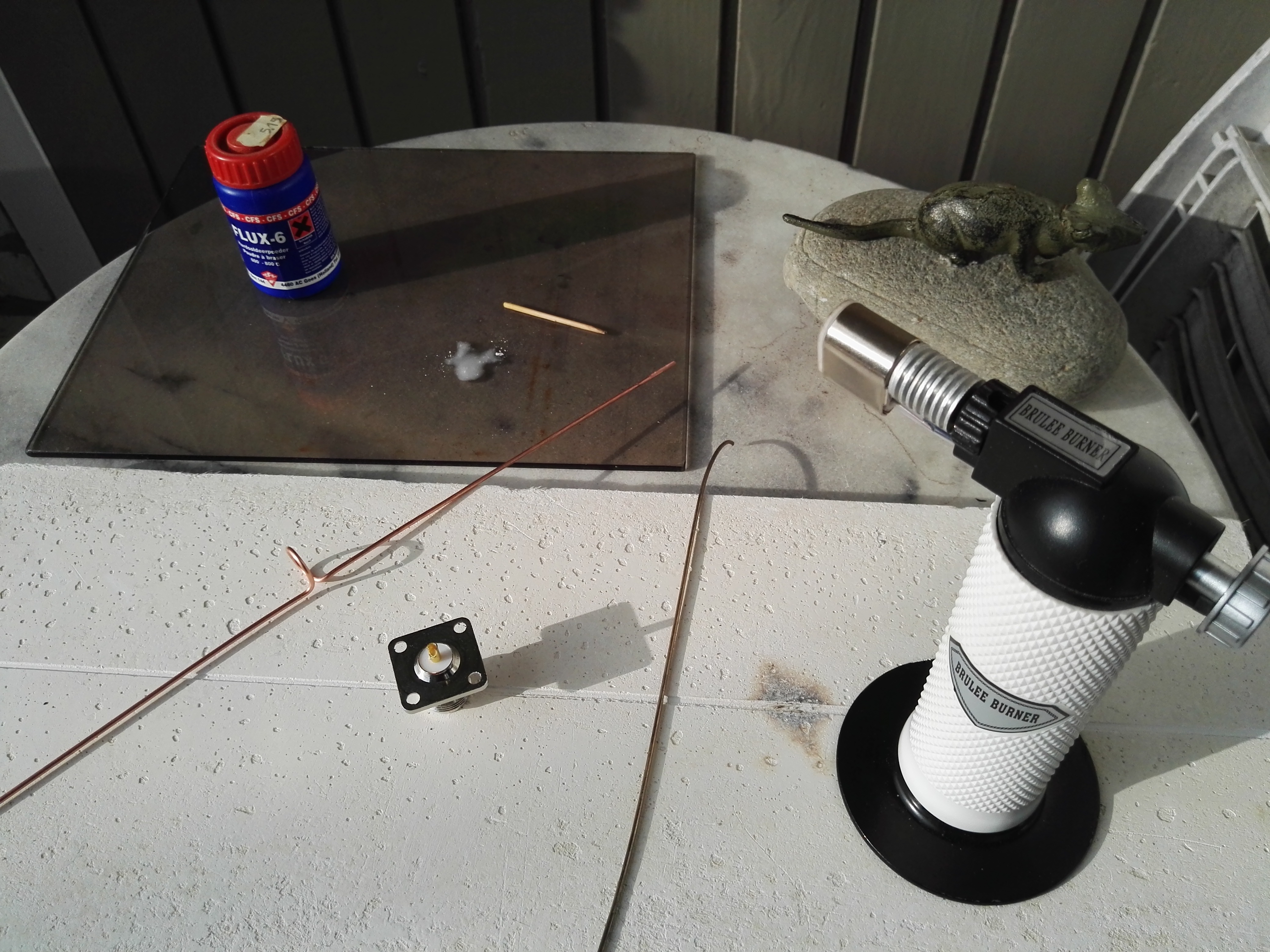
Hole at the last bend (top) is soldered with silver solder but can also be done with soft solder
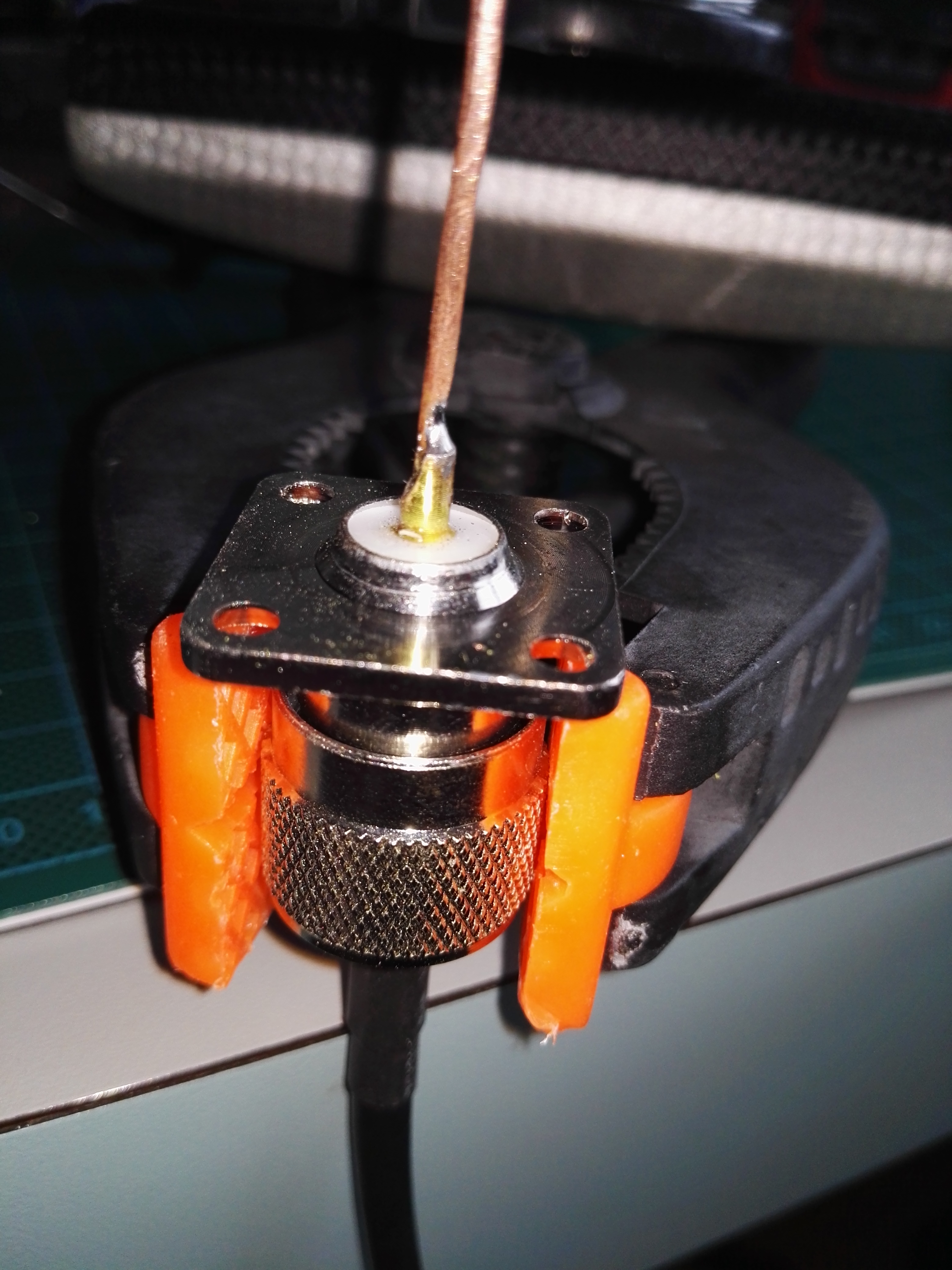
To prevent the middle contact from warping by heat, clamp the N male / female connector to solder the antenna perpendicularly
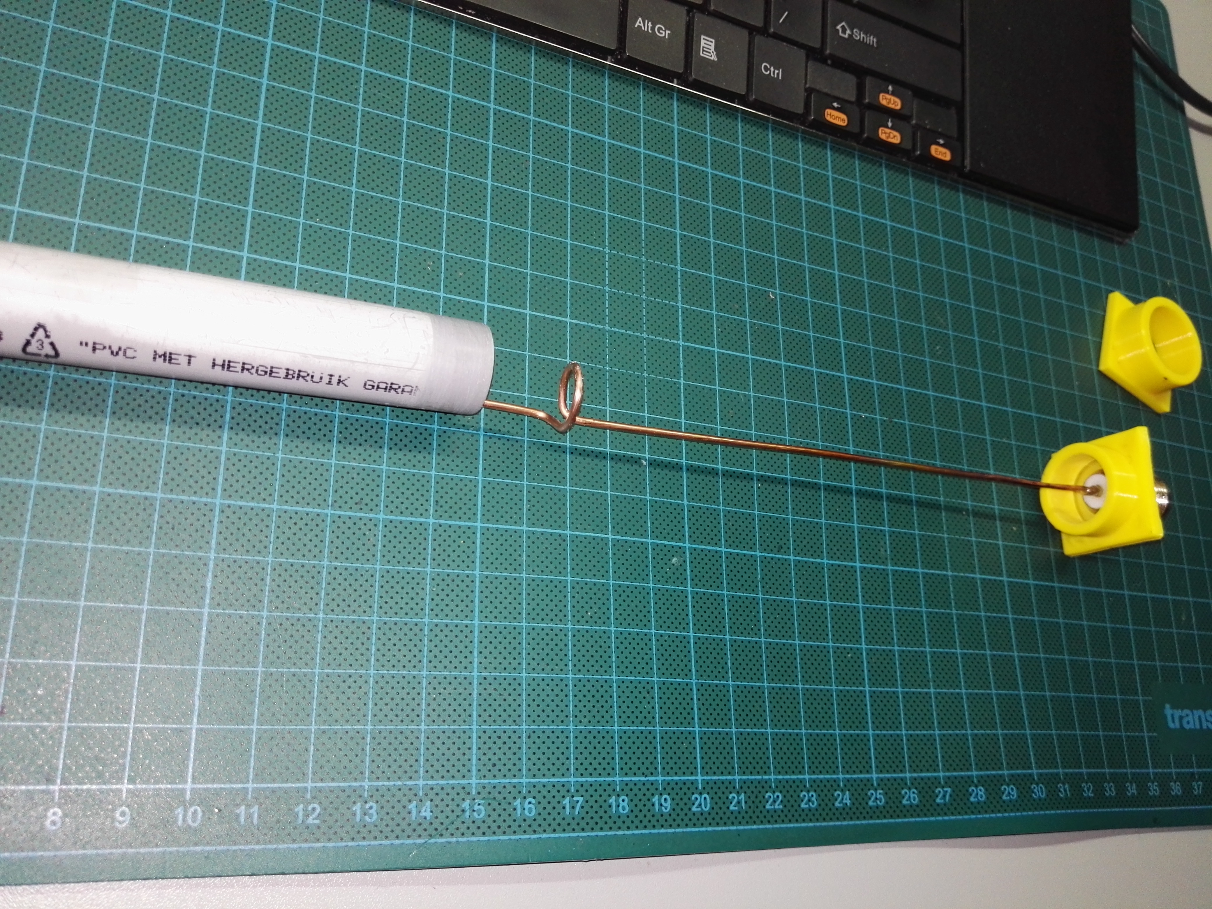
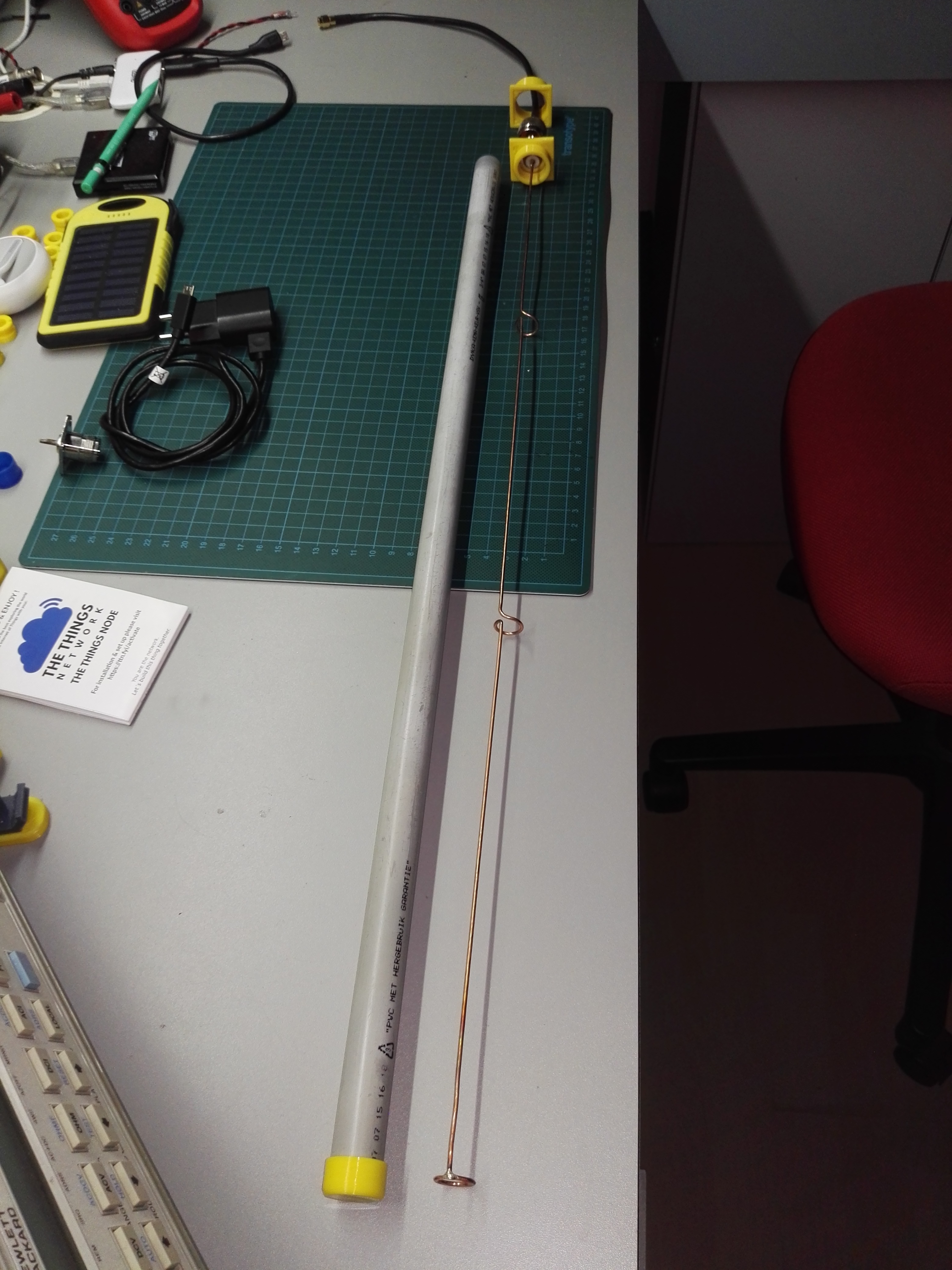
The loops have an outer diameter of 15 mm and fit into this 3/4 "tube.
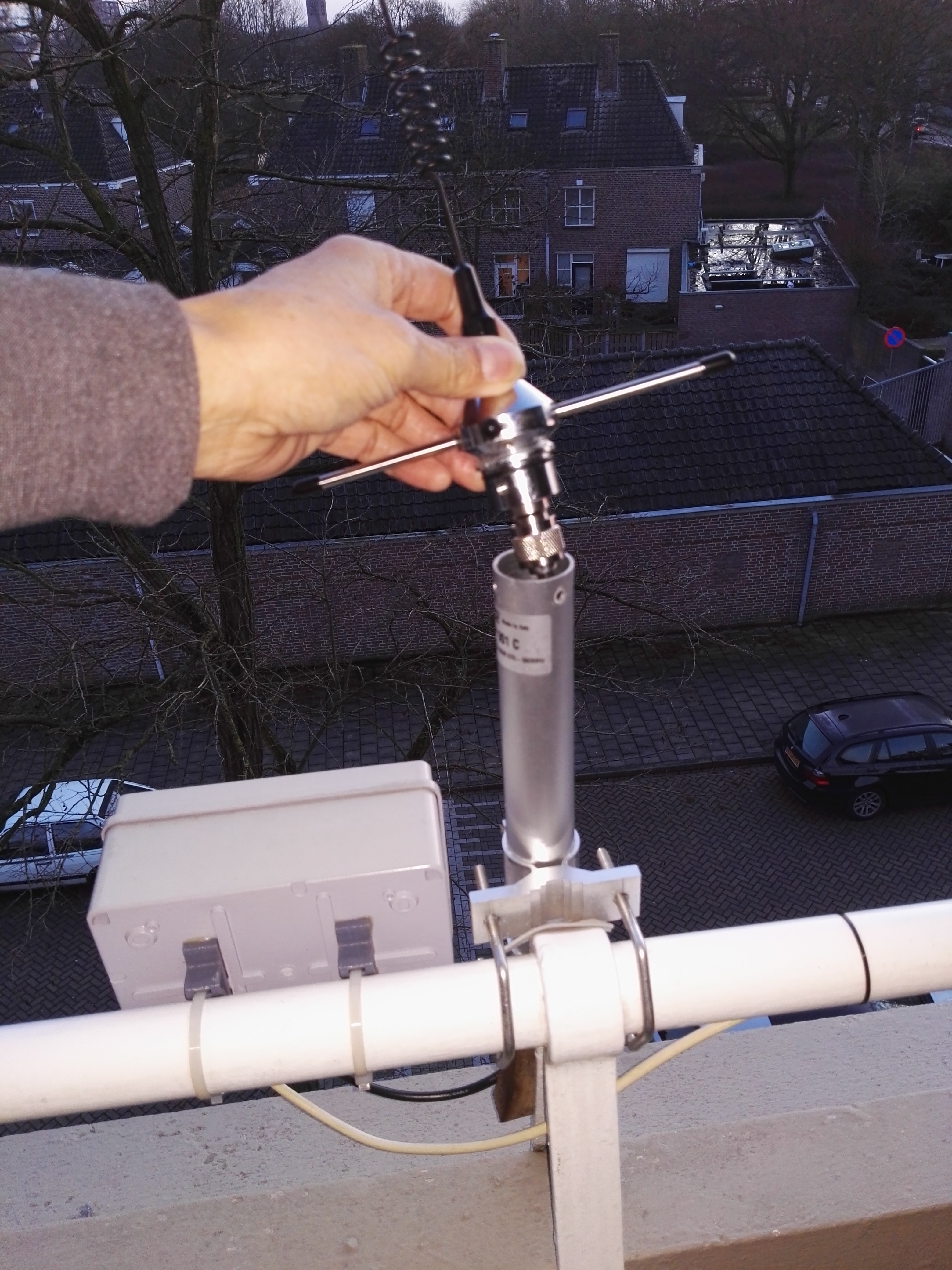
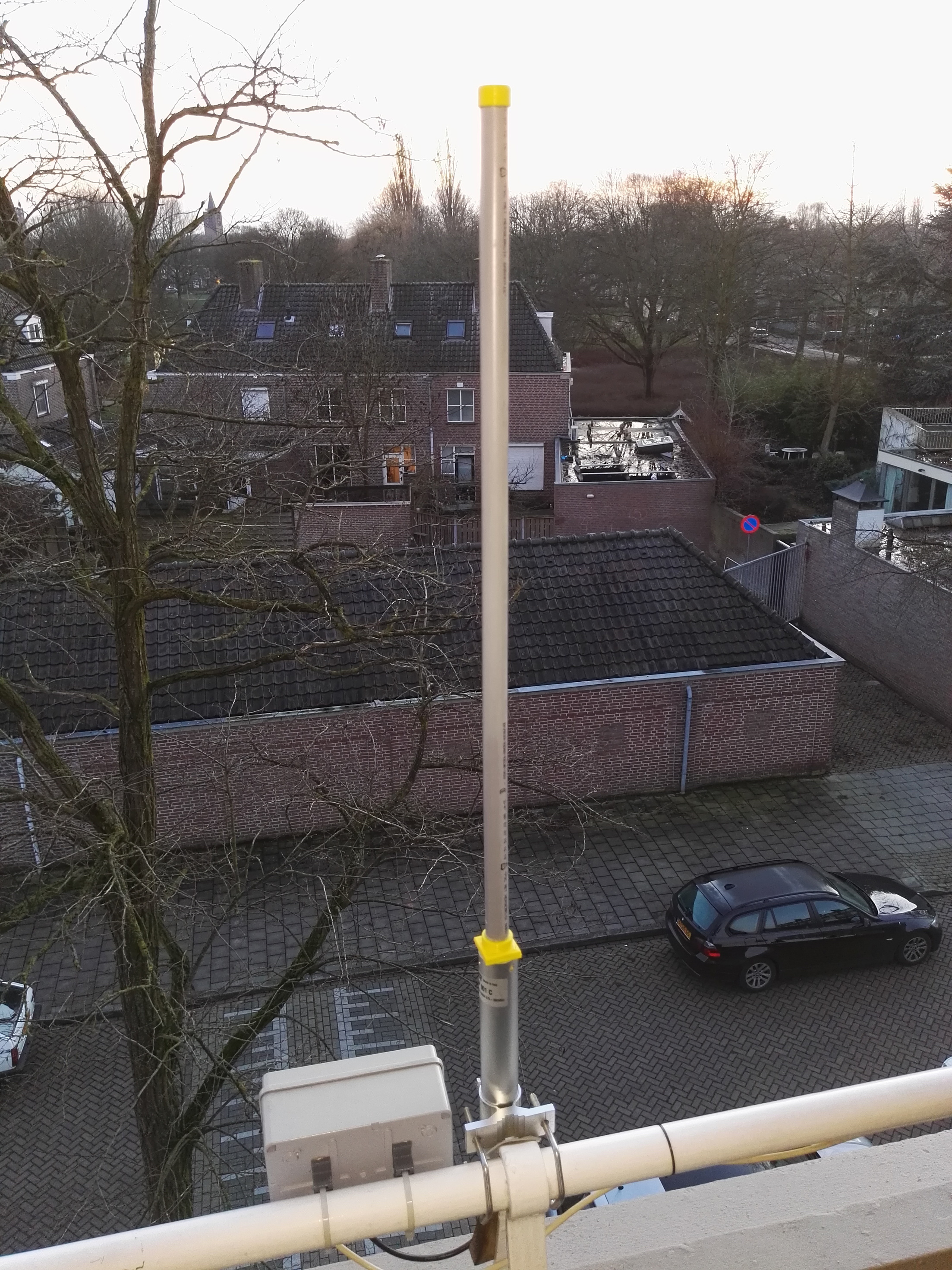
My Sirio is being replaced by the DIY Collinear.
Unfortunately, I do not have any measurement equipment except my nodes. In this form, the antenna seems less sensitive than the Sirio.
Before I changed the antennas, I constantly received “strange” node (26011620) SF11, RSSI -103, SNR -16.5. With this DIY Collinear I did not receive any data from this node in the last days …but this afternoon I placed the Sirio again a̶n̶d̶ ̶ ̶i̶t̶ ̶s̶e̶e̶m̶s̶ ̶t̶o̶ ̶m̶e̶ ̶t̶h̶a̶t̶ ̶t̶h̶i̶s̶ ̶n̶o̶d̶e̶ ̶i̶s̶ ̶n̶o̶ ̶l̶o̶n̶g̶e̶r̶ ̶a̶c̶t̶i̶v̶e̶ ̶ … conclusion, sensitivity still has to be investigated.
I have a really good ADSB antenna for 1090 MHz. 868 MHZ is close but not that close.
Could it be worth trying or will the bad swr offset the benefit?
your gateway transmits sometimes to… so a bad SWR will decrease range
Obviously. But I have a choice: Keep the current setup, gpa inside the roof or switch to the 1090 MHz on the roof… There’s the dilemma.
The switch is relatively easy. What I would really like is to switch the small gpa to the mast so it sticks above the roofline but this is at the moment a bit too much effort.
200MHz is way off imo. Imo even a 900MHz antenna is on the verge of acceptability.
The mismatch can also impact your VSWR, which means more power reflected back into the radio which is never good. Check your datasheet! 
I decided to ditch the adsb antenna and mount my gpa on that pole. Also I feel the need to show off this project because it is maybe the coolest antenna I had since my CB dx days.
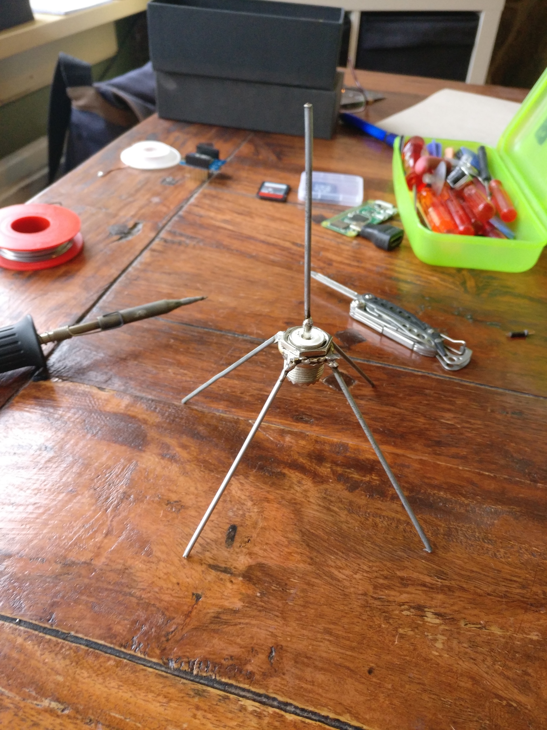
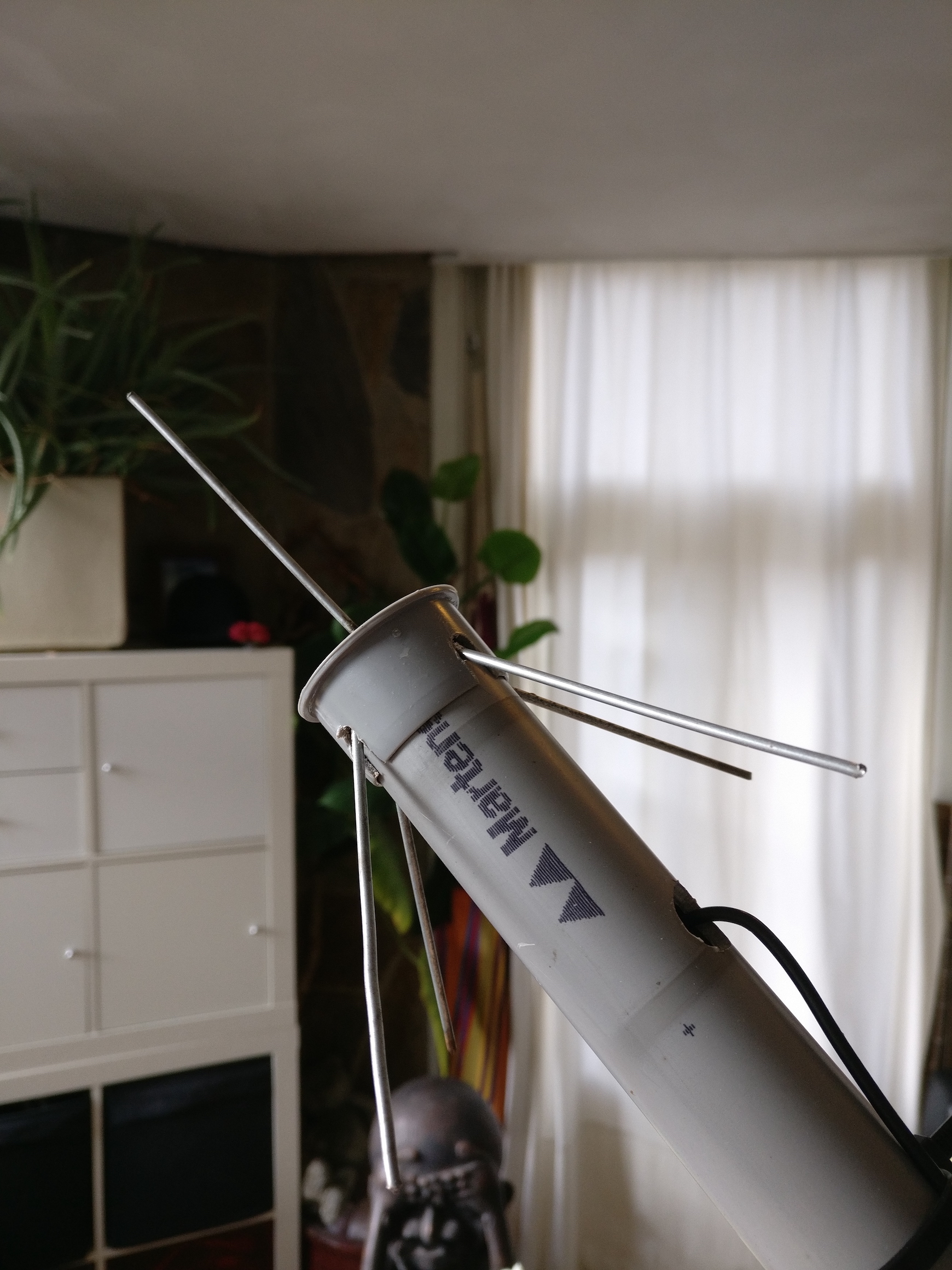
Well done! Looking great !
Thank you 
It is under the roof again but with some longer cable and better connectors. Performance is the same or better than without mast and with old coax cable.
Next step: weatherproof it with sugru and stick it outside. Hopefully soon!
Weatherproofing shouldn’t be necessary. The GPA can be put outside in its bare copper form. Mine is up there for a year now  .
.
True. Sometimes it can be fun to over-engineer, I must at least stop the cap from blowing off.
How is you gpa doing? Care to share some mapper data?
A little corroded but working like on the first day. It’s back on my desk now, I’ve replaced it with this baby and moved it to another location which reset the mapping data. Right now waiting for the IT guys to patch me up so I can test the new guy  .
.