The range is only 10m ?
You would probably get that range if you put a terminator on the antenna socket and put the whole gateway in a tin box.
The range is only 10m ?
You would probably get that range if you put a terminator on the antenna socket and put the whole gateway in a tin box.
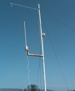
Colinear Ant for LoRa GW
http://e.pavlin.si/2018/04/03/colinear-antenna-for-868mhz-lorawan-gateway/


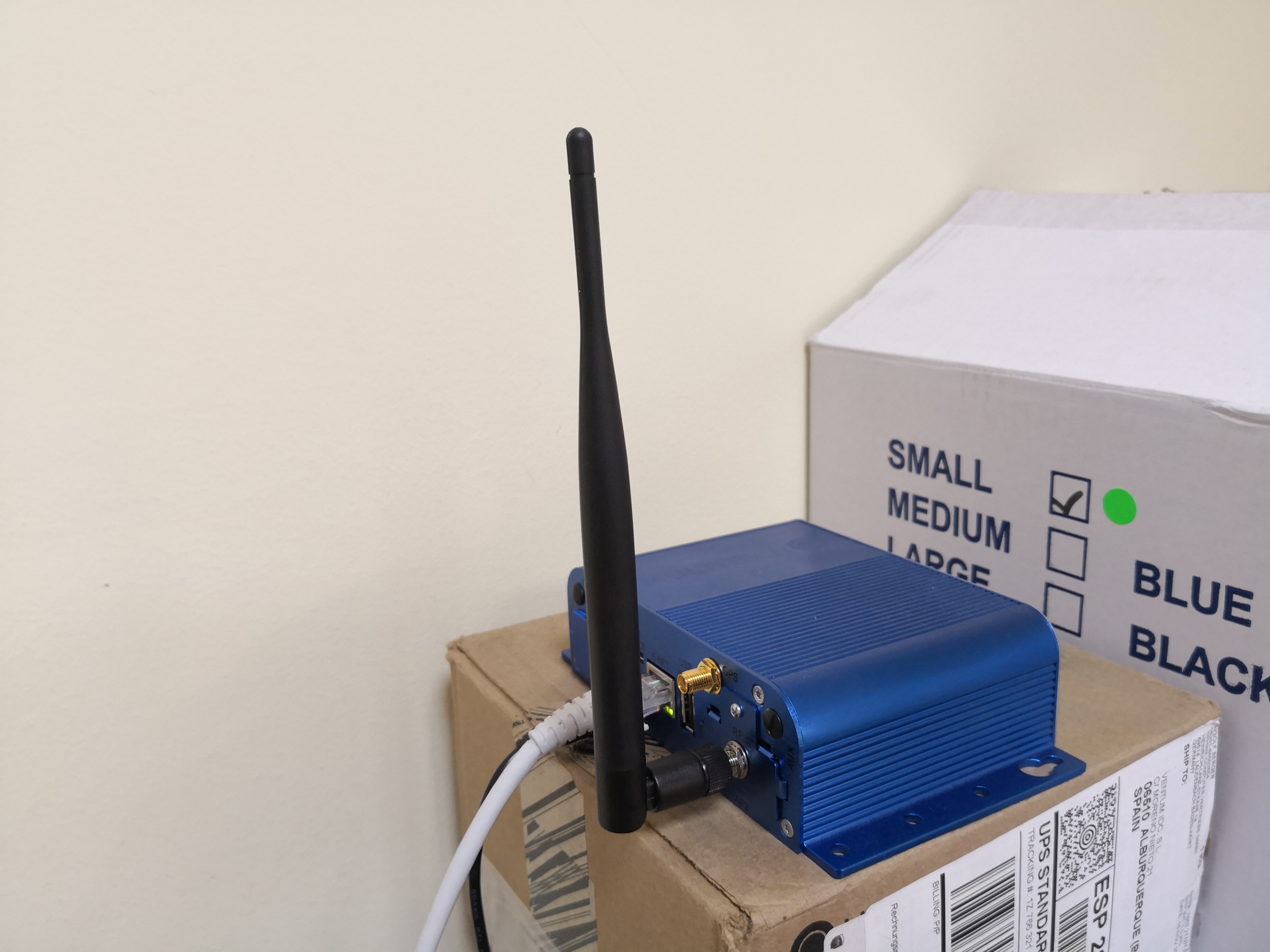
Only getting 10 metre range I would suspect you don’t have an antenna connected to the “Conduit”. Have a look at the SMA connector on the back of the Conduit and on the bottom of the antenna. Check that one has a centre pin and the other a central socket. SMA connectors come in both Normal and Reverse Polarity, I would suspect both the Conduit and the Antenna both have central sockets and there is no electrical connection between the Conduit and Antenna.
True History…

I’m so stupid…
The antenna was not connected to the Lora card, it was connected to GPS … I realized now when taking a photo to upload it.
Now the coverage is superior. Anyway, it’s a basic antenna and I’m going to change it to a more powerful one like the Sirio GP 868 C.
Thanks for the answers
Have you yet managed to check GW with correct ant placement? As a general guidance is don’t operate unit with no antenna as reflection and lack of load means chunk of Tx pwr ends up back in the chip causing damage or long term reliability issues…if, when you swap back, you find problems that is a good place/assumption to start from if it looks like it isn’t working hereafter! 
Suggest you configure start up with much reduced TX then gradually wind the wick up to higher power operation once you know all ok 
 ) the original post disappeared … so here it is again (sorry)
@ferrero, wonder if you could comment about the two Lora Collinear antennas you designed. To keep a slim design, were the antennas designed to be connected to a Sleeve Balun rather radials forming a ground plane? Also the diameter of the 915MHz version is a lot smaller than the 868MHz version. Could you comment as this is much smaller than simply scaling the dimensions of the 868MHz version due to frequency shift.
Interesting gain figure too.
Wonder if that is a theoretical (modeled gain) or real world ?
If someone wants to buy it and send it to me I would test the gain, no charge.
Could you spin it out to a complete book?
Although there are some users on the 433 and 160 ISM bands by far the main focus here would be restricted to 868/915M for base stations and then the far more difficult task for ‘things’.
Recent low cost technology has bought some quiet advanced equipment into the range of the amateurs reducing the task into producing good, narrow band, designs with sufficient gain to be usable, repeatable and of course legal. Quite a task.
On the node, the physics of the monopole and dipole designs is covered in your dry references but then of course these need to be related to local conditions and propagation use in the ‘real world’. Further, little lengths of wire, board mounted ceramic resonators and direct PCB layouts as radiators start to become a real ‘black art’. Yes, you are right – quite a book! 
@dicktonyboy, watched with great interest your youtube video modelling a monopole with 4NEC. Did you proceed and model a colinear? I understand they are a challenge to make, so was interested in your experience modelling and converting this into the real world.
ah thanks Tony … the road to hell … the modelling was really time consuming and I failed to find a simple method of parameter passing - I THEN got dragged into physically building some small wire examples and fell into a time sump. It is however still on my list as a major interest.
Hope you eventually find time. I’ve been trying a number of 868 and 1090MHz designs and converting them to 915 for Australia. Not having much luck in the conversion. Simply scaling the dimensions linearly using the ratio of the two frequencies. The photos I see don’t have a ground plane and I suspect they use a sleeve balun to stop currents flowing down the coax outer. The VNA I’m using is showing they are not even tuned close to 915MHz. Do you have a recommended concept for a colinear? I’m now looking at a phasing harness between several dipoles.
The ground plane is vital afaic (it make characterising so much simpler and stable) as is tight control over the gap in the coil (which may be seen as just a phase delay in the vertical stack). Fabien sent me a design I must forward to you.
@dicktonyboy. I have downloaded the Fabien’s two antenna designs from GitHub and when I look at the photo on the IRNAS site it looks like a Sleeve Balun on the bottom of the antenna. There’s certainly no radials in that photo. There are no assembly details as yet on that site, so i’m not 100% sure about its final design. Interested to see the design you have.
Hi Tony,
I asked the guy from IRNAS and he told me the black piece you see on the bottom side of the antenna is just a pice of plastic to make it more rigid.
Thanks @kylix, if the black device was not a balun but a piece of plastic I wonder how the IRNAS gateway performed as the VSWR without a groundplane is high. 4:1 @LoRaTracker tested these antennas some time ago and reported the results to be something like 4:1