Hello to all
I can agree that cable length has a certain influence on VSWR. I experienced that already, when installing 3&4G GSM-antennas in a previous life, VSWR could be worsened or improved notably by leaving or cutting a few millimeters of the coax length. I was lucky enough to be working with Anritsu sitemasters then, but actually for LoRa development activities, I only use an N1201SA and it shows similar results for cable length influence.
I tested a cheap waterproof antenna like pe1mew in The BIG and SMALL ANTENNA topic part 1 , but also 2 long whip antennas from RAK Wireless and 4 short whip antennas from TTGO and Heltec, all for 868 MHz.
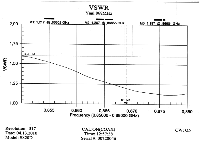
The waterproof antenna got about half a meter of cable fixed on it, so I had to use that anyway. But since this cable length is about 3 times the half-wavelength @868MHz, it should have only little influence on VSWR (but minus a few gain so not really ignored, Costo!). On testing indoors, I found very high VSWR’s due to reflexions of the walls. Once mounted outdoors on the roof, it showed quite good VSWR lower than 1.3,so I think this antenna is not so bad at all (@pe1mew: maybe this confirms BoRRoZ’s good results?).
Then I went for the whip antennas, and found that the fact of testing them indoors had little influence on any of them, as they all gave about the same VSWR indoors and outdoors. Two of them (a long RAK and a short TTGO whip) gave the lowest VSWR of 1.0 over a large band in the 868 range.
So I decided to test those two antennas, once mounted directly on the vector analyzer standing on a desk, then lying horizontally on the desk, and finally mounted on a stand and sequencially tested with cable extenders of 25, 17 ,16 and 15 cm. You have to add about 2x1 cm to the cable length if you count it strictly from pin to pin, so only the 15 cm extender cable got around the half wave length of 17,27 cm… and this makes sense, as all cables gave VSWR between 2,3 to 6 and more when using the extensions, except the 15 cm extension which got 1.7 VSWR !
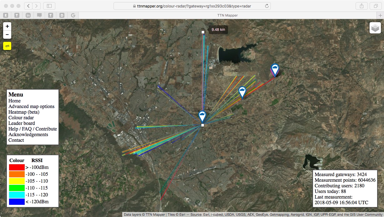
We just placed our 3rd gateway in Temecula wine country. The antenna is a 6 dBi omnidirectional installed on the roof of the winery. TTN mapper shows 9.5 km range, and we could probably get more with stations placed at high locations. We tested range with the gateway indoors, just got a few blocks away. Big improvement!
You may also use a very easy to build antenna, that provides ~2dB gain, while being electrically short cutted, which increases parasitic rejection: The J-Pole antenna. You may ust this calculator to determine the dimensions:
http://hamuniverse.com/jpole.html
At 867 MHz your antenna will be ~25cm long and will fit into a 16mm electrical plastic conduit.
At the base of the antenna I have winded 3 loops of the coax cable to symmetrize the signal (balun).
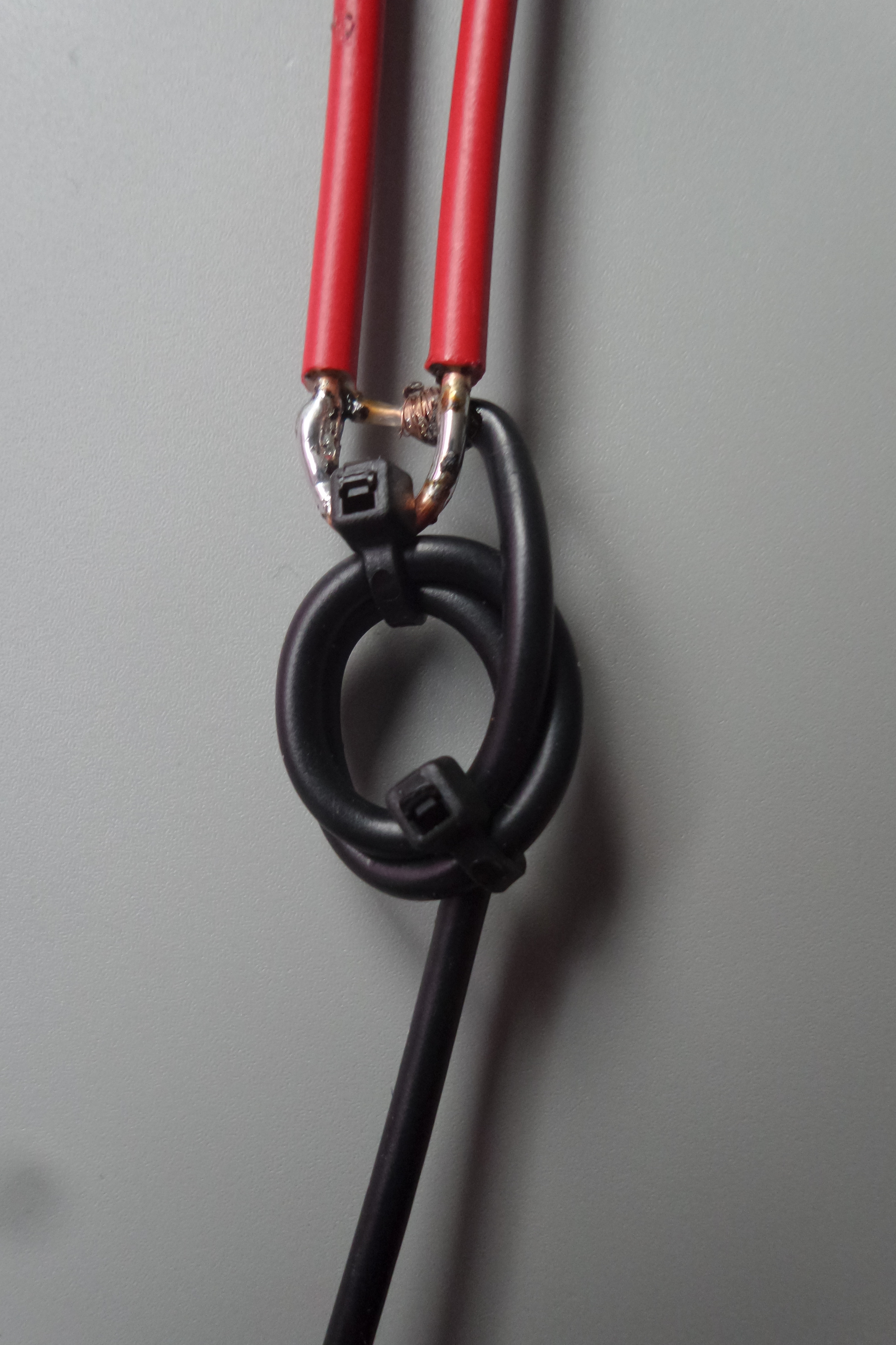
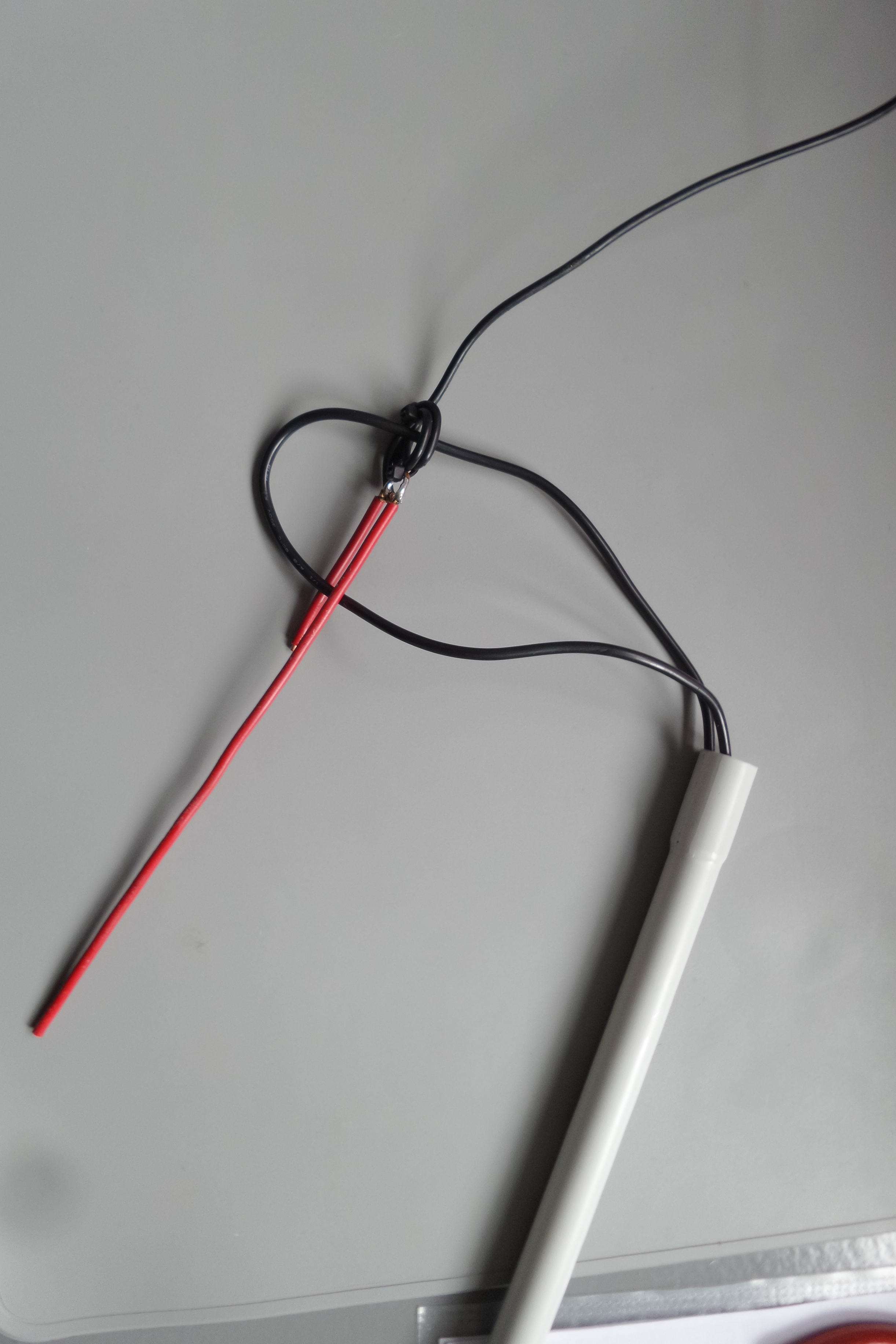
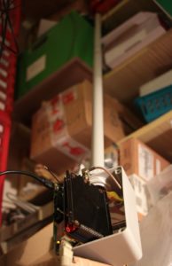
The antenna is built in minutes…In the last picture the black wire loop was just used transiently to pull the antenna into the plastic conduit without staining the balun loops.
Hello,
I currently own a “Multitech Conduit” gateway with a basic antenna and short range (10-15m).
I would like to acquire an antenna (868MHz) with much more range but I can not find any with enough information.
What antenna would you recommend to me with a greater scope? For outdoor.
Thank you!
The range is only 10m ?
You would probably get that range if you put a terminator on the antenna socket and put the whole gateway in a tin box.
Colinear Ant for LoRa GW
http://e.pavlin.si/2018/04/03/colinear-antenna-for-868mhz-lorawan-gateway/
Only getting 10 metre range I would suspect you don’t have an antenna connected to the “Conduit”. Have a look at the SMA connector on the back of the Conduit and on the bottom of the antenna. Check that one has a centre pin and the other a central socket. SMA connectors come in both Normal and Reverse Polarity, I would suspect both the Conduit and the Antenna both have central sockets and there is no electrical connection between the Conduit and Antenna.
True History…
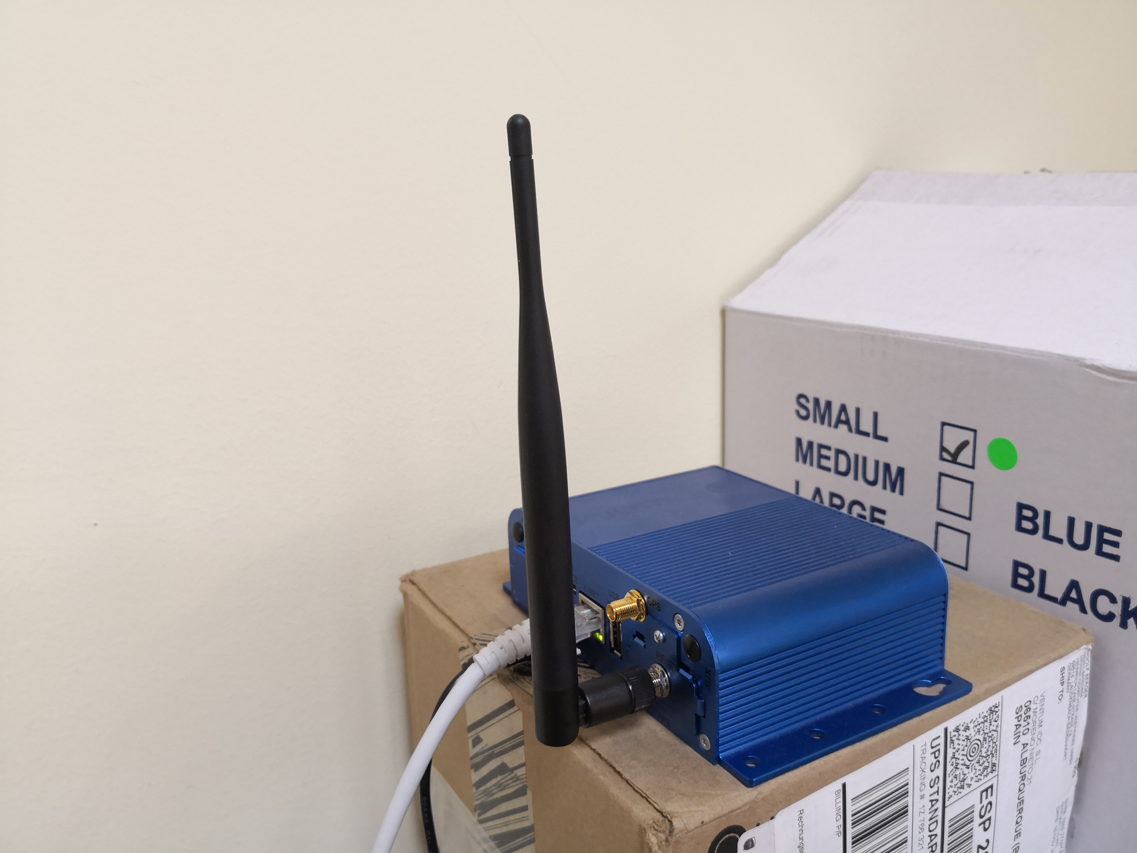
I’m so stupid…
The antenna was not connected to the Lora card, it was connected to GPS … I realized now when taking a photo to upload it.
Now the coverage is superior. Anyway, it’s a basic antenna and I’m going to change it to a more powerful one like the Sirio GP 868 C.
Thanks for the answers
Have you yet managed to check GW with correct ant placement? As a general guidance is don’t operate unit with no antenna as reflection and lack of load means chunk of Tx pwr ends up back in the chip causing damage or long term reliability issues…if, when you swap back, you find problems that is a good place/assumption to start from if it looks like it isn’t working hereafter! 
Suggest you configure start up with much reduced TX then gradually wind the wick up to higher power operation once you know all ok 
because of human error (me
 ) the original post disappeared … so here it is again (sorry)
@ferrero, wonder if you could comment about the two Lora Collinear antennas you designed. To keep a slim design, were the antennas designed to be connected to a Sleeve Balun rather radials forming a ground plane? Also the diameter of the 915MHz version is a lot smaller than the 868MHz version. Could you comment as this is much smaller than simply scaling the dimensions of the 868MHz version due to frequency shift.
Interesting gain figure too.
Wonder if that is a theoretical (modeled gain) or real world ?
If someone wants to buy it and send it to me I would test the gain, no charge.
Could you spin it out to a complete book?
Although there are some users on the 433 and 160 ISM bands by far the main focus here would be restricted to 868/915M for base stations and then the far more difficult task for ‘things’.
Recent low cost technology has bought some quiet advanced equipment into the range of the amateurs reducing the task into producing good, narrow band, designs with sufficient gain to be usable, repeatable and of course legal. Quite a task.
On the node, the physics of the monopole and dipole designs is covered in your dry references but then of course these need to be related to local conditions and propagation use in the ‘real world’. Further, little lengths of wire, board mounted ceramic resonators and direct PCB layouts as radiators start to become a real ‘black art’. Yes, you are right – quite a book! 
@dicktonyboy, watched with great interest your youtube video modelling a monopole with 4NEC. Did you proceed and model a colinear? I understand they are a challenge to make, so was interested in your experience modelling and converting this into the real world.
