Some dated but nice Antenna Fundamentals videos
Propagation
Directivity
Bandwidth
Nice video.
All the time I had been testing antennas with RSSI in that way I did not think to setup the test software such that the ‘receiver’ would respond back to the transmitter with the RSSI of the incoming packet.
Although my HAB tracker software (2015) by default will respond to an incomming command with an ACK or NACK packet that included the SNR and RSSI of the incoming command.
With a third LoRa device as another receiver you could improve the test further by standing well away from the trasnmitter and receiver path and counting the test packet RSSIs in that way.
The test software that Andreas referred to that I have been using is the Ping test software that is here;
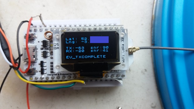
I’ve been measuring the TX and RX RSSI recently and got these figures - slightly dubious of the RX figures though ( I know the TX SNR should have a decimal point)
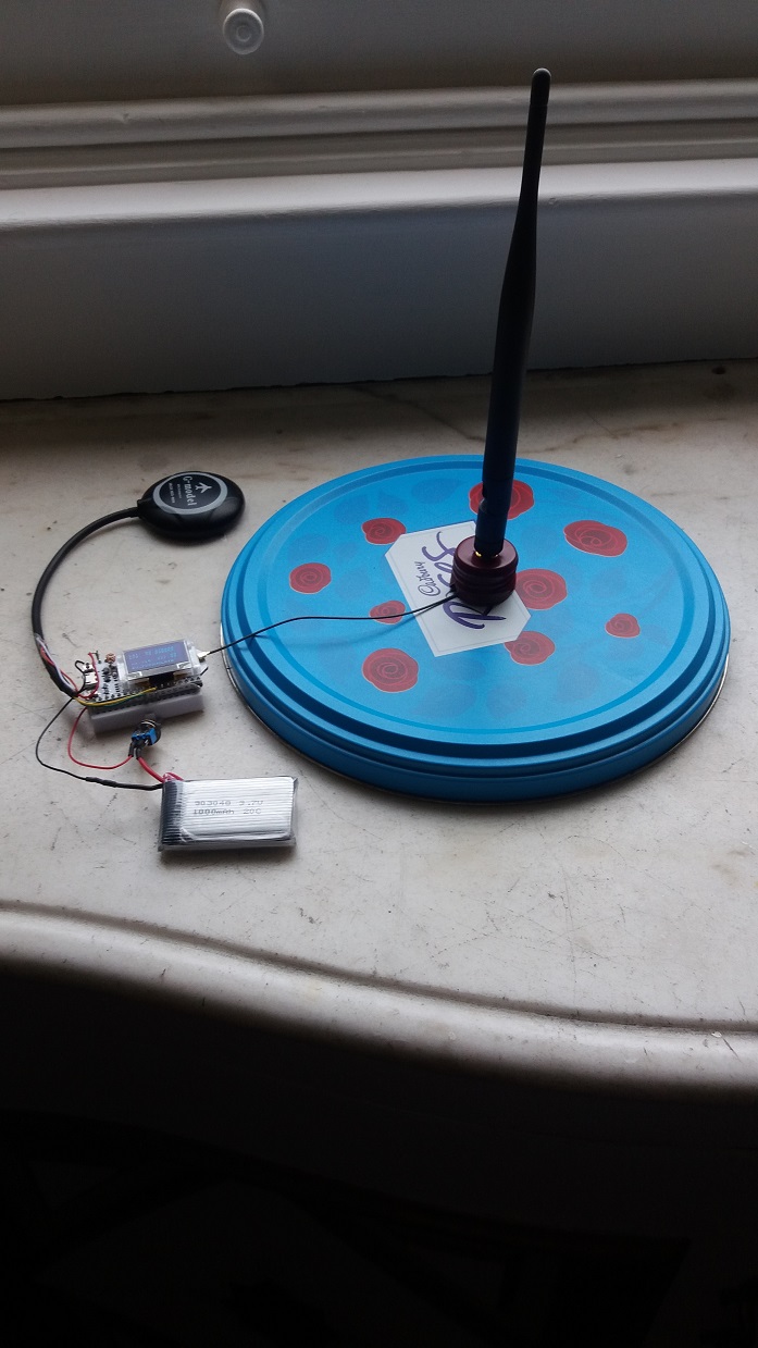
N.B. The temporary antenna stand is an old wine bottle top!
I’ve been wondering what to put it all in. An old glass jamjar could work, but of course, the glass is breakable 
Something looks wrong, if your software is reporting RSSI correctly, how can you get a link difference of 43dBm (-63 and -20) ?
I know the TX values are correct (I can see the same values reported in the TTN console).
For the RX side, I’m just reporting local variables LMIC.rssi and LMIC.snr.
Does anyone know the right way to calculate this? one thought is to subtract 137. However, wandering around outside gave consistant values for the TX side, but crazy values being reported for LMIC.rssi and LMIC.snr. ![]()
To my (limited) knowledge RSSI stands for Received signal strength indicator.
Assuming:
RSSI measured on the node is the strength of the signal received from the gateway.
RSSI measured on the gateway is the strength of the signal received from the node.
What (on the node) is RSSI of TX?
Its the RSSI that was measured on the gateway for the previous transmission ( i.e. it is “gateway” data that was downlinked back to the node) . This is working OK.
It seems the problem is the other RSSI value i.e. the measurement on the node of the signal strength of the downlink from the gateway.
The LMIC variable LMIC.rssi (on the node) doesn’t have a value which makes sense.
I’m thinking there must be some sort of adjustment needed (perhaps an indication of different SF and shifting of the value?) . Does anyone have ideas where to look?
I’m trying to compare the effect of different antenna for both directions. One would think it woudl be roughly the same, it would be nice to prove it really,
How does that work? Does this happen automatically (e.g. in response to OOTA join request) or do you send it explicitly in a custom downlink message?
@CurlyWurly I was struggling with the same issue about the rssi value.
LMIC, RadioHead, HopeRF, and Semtech all use different values.
The semtech datasheet says this.
RSSI[dBm] = -157 + Rssi (using HF output port, SNR >= 0)
or
RSSI[dBm] = -164 + Rssi (using LF output port, SNR >= 0)
(see section 5.5.5 for details)
and in section 5.5.5
The constants, -157 and -164, may vary with the front-end setup of the SX1276/77/78/79 (LnaBoost =1 or 0,presence of an external LNA, mismatch at the LNA input…). It is recommended to adjust these values with a single-point
calibration procedure to increase RSSI accuracy.
So with LnaBoost enabled I used this function int16_t rssi = (readReg(RegPktRssiValue) - 157);
and for the snr value float snr = ((int8_t)readReg(RegPktSnrValue)) * 0.25;
But I am not 100% sure. 
Agreed its confusing, and there have been changes since the original datasheet.
Whilst the absolute value of the RSSI will change depending on whether you use -157 or -164 or whatever, is it of much consequence, as long as the RSSI remains linear ?
(although see note 3 in 5.5.5)
Thanks guys - The RX SNR is looking better now
In the end, I used the following code to calculate the values (N.B. RSSI_OFF is 64)
int16_t   rssi = (LMIC.rssi - 64);
int       snr  = LMIC.snr * 0.25;
N.B. In lmic.cpp there is reference to
getSensitivity(LMIC.rps);
But that seemed to make the values worse - so I ignored it 
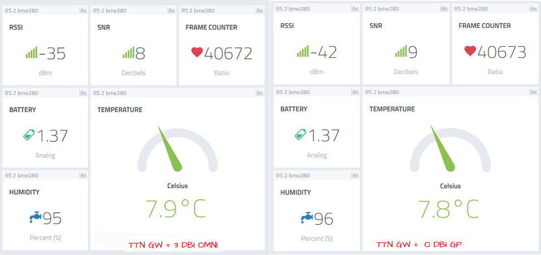
I’m glad I just spotted your post, had one working here for a few months with some success but now its struggling with the weather elements and I’m going to replace it next week - odd thing is it failing on transmit I think, anyway its going in the bin shortly
How do you get the battery widget? I see they’re listed as “Coming Soon” - do they actually work yet?
What happens to the RSSI at a gateway when a BIG antenna is replaced with a SMALL antenna?
I have a test gateway in my worskshop. It has been using a Taoglas OMB.868.B05F21 collinear dipole array which is a typical BIG 5dBi high-gain antenna, 1m long, in a white fibreglass tube. This has been replaced with a SMALL Taoglas MA120.A.QP.001 -5dBi gain “puck” omni antenna mounted on a 25cm x 25cm steel plate ground-plane. No other changes.
I have a test “thing” outside, about 25m away and through 2 masonry walls sending uplinks every 2 minutes.
The average gateway RSSI for uplinks from the test thing with the BIG antenna on the gateway has been -65dBm. Range is -62dBm to -67dBm.
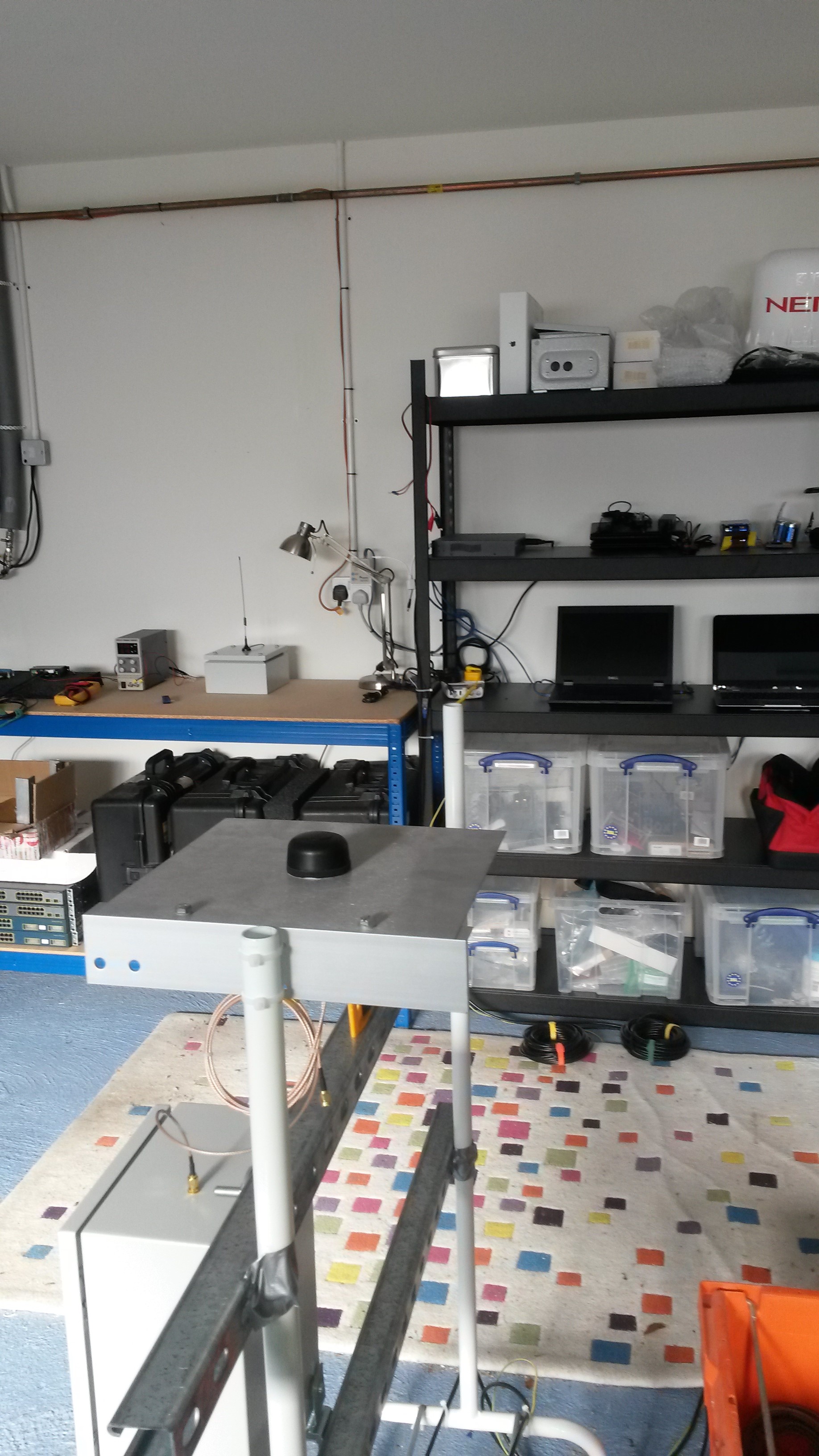
Here’s a general picture of the gateway with the new SMALL Taoglas puck antenna.
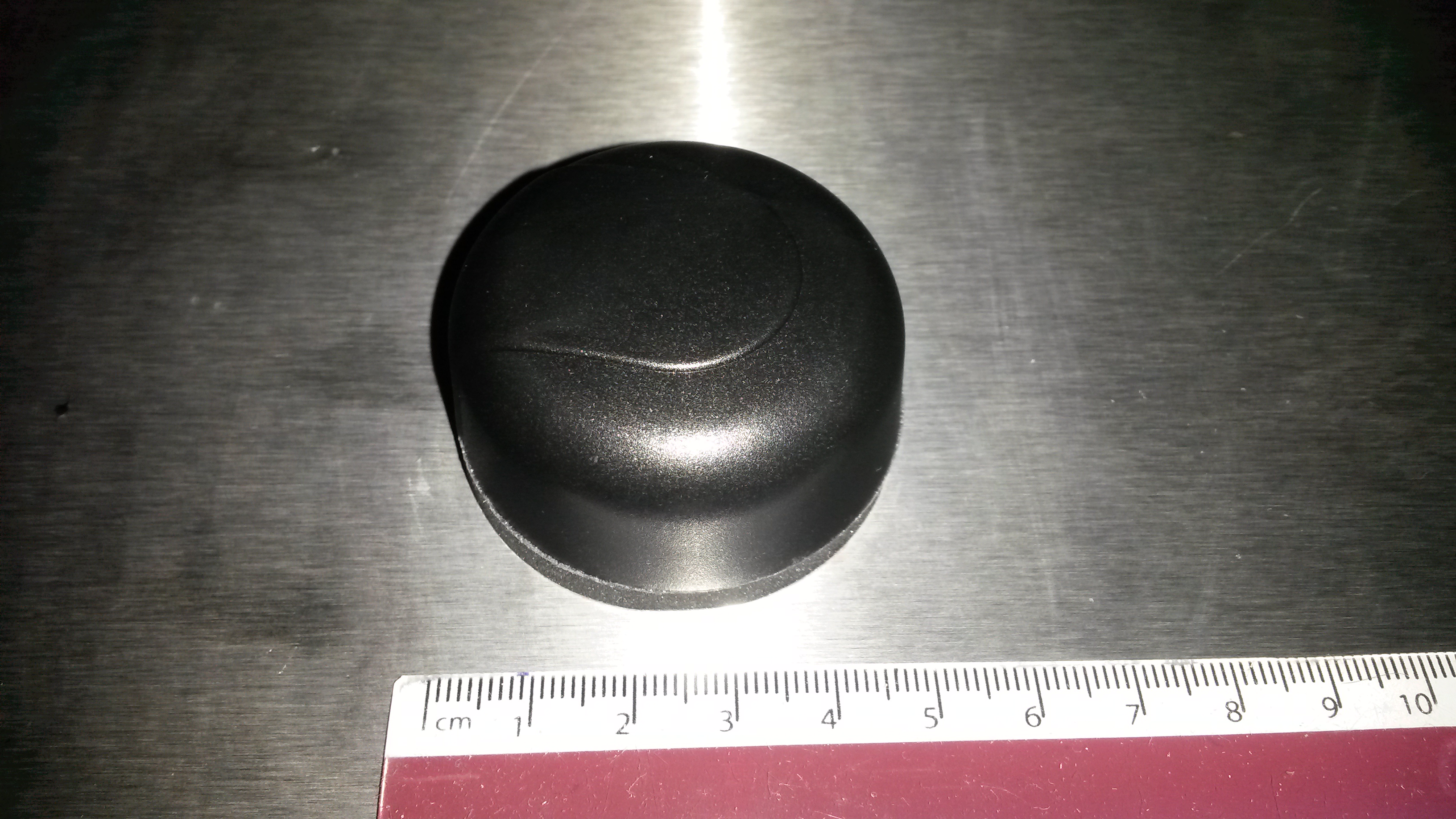
Here’s a close-up of the new SMALL antenna - under 5cm in diameter.
My estimate of the new average RSSI was that I would lose between 10dB and 15dB. 10dB as the difference between a +5 gain antenna and a -5 gain antenna and then up to another -5 because my ground-plane is smaller than Taoglas recommended 50cm x 50cm ground-plane and because I’m an “antenna pessimist” and because Taoglas bluntly calls this a “short range antenna”.
I now have the new average RSSI. What does the collected wisdom of the forum think the new RSSI will be? Please make your estimates by replying to this topic. A well-done will be awarded to the nearest response(s).
The sensor is at the same height as the antenna?
He used an analog widget, he changed the icon to battery and it’s name ![]()
Yeah, have since figured it out.
A great “Aha, that’s sneaky!” moment 
