Rak811 Tracker Board

You mentioned you maybe able to provide some “how to lab file” I have my board hooked up via the recommended CooCox setup and able to compile the file successfully and copy it via the Segger Jlink to the board. However I must be missing some values in the main.h as I can not make it work. The hardware looks good but support is very limited. Can you help? maybe you have a main.h file you can comment on the values which have to be changed. I’m new to this and it has been a real challenge.

I’ve got now everything worked, Also GPS is working (seen with printf in main.c).
After starting the debugger I see only activation at ttn console, but no further payload.
Does anyone has an idea why.

@rakwireless can I suggest a poss improvement/change to board design. Playing with a few 811 tracker and sensor boards it seems that as soon as either USB pwr or a battery connected the device kicks in with no way to shut down other than disconnect battery or remove usb power - indeed need to disconnect both. I am building into small housings with just usb and Ant connections exposed with (now difficult to access) rechargeable batteries embedded and its annoying that operation starts immediately and batt life obvious starts to run down.

From a quick scan of schematics it looks like the EN pin of the MIC5219 3.3v regulator is hard wired to VBatt. If I understand correctly then if that pin left open or brought low device shuts down down stream of the regulator with v. small quiescent current or poss charging current from USB if on charge. Is it poss to change design to bring that pin to a header that can then either be jumpered high (say on a 0.1inch pair) for those who want always on or brought out to a simple spst switch to take high for those who want a basic on/off function? That also allows for device core to be off but USB pwr then used to charge battery as and when needed. Please advise options/practicalities as may have to switch to alternate board type (alt vendor) or commission custom design if I cant resolve, thanks.

If any forumites have alternate solution please shout!

2 Likes

+1

I’m just starting with this board, and that would be critical for my applications. Would love to be able to make use of a pre-existing design, but otherwise will have to do my own. Once I’ve evaluated the RAK811 module I can determine if it is suitable to use in my own design - so at least the sample board is helpful for that.

Anyone here know how to display the current voltage (or charged percentage) into Cayenne? There are blocks of code in board.c but I thought I should ask while I dive into the code.
I think there’s a debug message coming from the serial output with battery voltage so it’s definitely do-able I reckon.

How to Edit and Upload the code without a J-Link on Win10 and Atom

Download Atom.

Once Download, install and open Atom up.

Then go to settings > install, search for platformio

Install the following.
platformio-ide-terminal
platformio-ide
platformio-ide-debugger

Once done, download and install the comm drivers for the RAK811
http://docs.rakwireless.com/en/RAK811%20TrackerBoard/Tool/CP210x_Windows_Drivers.zip

Then download the git from OlofAst

open Atom, on the PlatformIO Home Tab, go to Platform

Search ST STM32, Install
Then click Reveal

It will open up a Explorer window, then open folder ststm32/boards
copy the file from OlofAst’s git, rak811.json to the ststm32/boards folder.

Then in Atom, click open folder.

Open the folder RAK811_BreakBoard from OlofAst’s git.

Then open the Terminal in Atom

To edit the DevEUI and etc… open the file src\Commissioning.h

Save, and close the tab.

Now to Compile.

In the Terminal window in Atom type: pio run

if you see SUCCESS, compiling went ok

Calculating size .pioenvs\rak811\firmware.elf
text       data     bss     dec     hex filename
53236      1628    5244   60108    eacc .pioenvs\rak811\firmware.elf
===[SUCCESS] Took 12.25 seconds 

Now to Upload .bin file to the board

Change the jumper on the board.
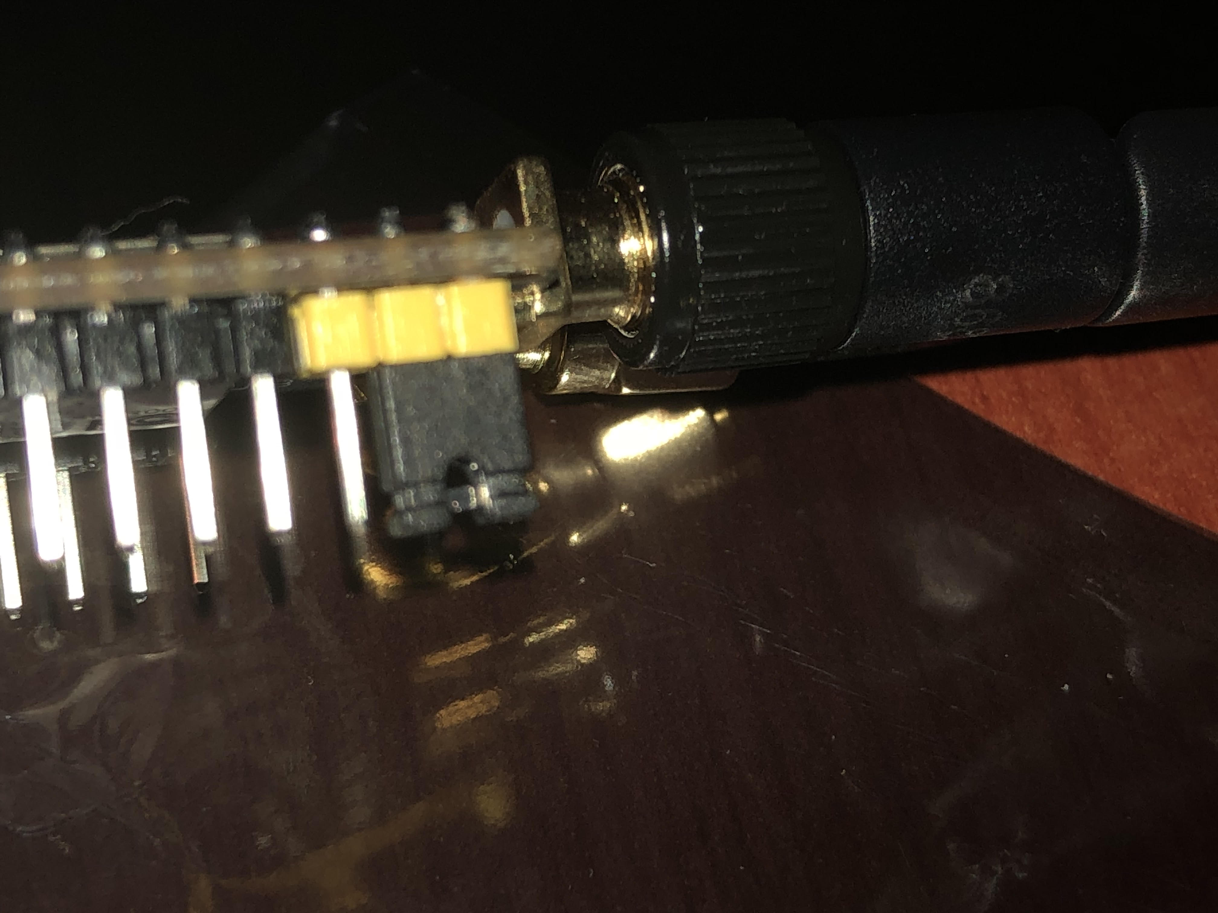
unnamed

Connect the usb, go to Device manager and check what is you comm port number for the board.

Then in the terminal window In Atom, run the following

stm32flash_src/stm32flash.exe -w .pioenvs/rak811/firmware.bin COM5

This will upload the .bin file, the result should be

stm32flash 0.5

http://stm32flash.sourceforge.net/

Using Parser : Raw BINARY
Interface serial_w32: 115200 8E1
Version      : 0x31
Option 1     : 0x00
Option 2     : 0x00
Device ID    : 0x0429 (STM32L1xxx6(8/B)A)
- RAM        : 32KiB  (4096b reserved by bootloader)
- Flash      : 128KiB (size first sector: 16x256)
- Option RAM : 32b
- System RAM : 4KiB
Write to memory
Data size: 54868 bytes
Erasing memory
Wrote address 0x0800d654 (100.00%) Done.

You should all be done. Unplug, change the jumper back to original position.

Power up the board and it should connect to the AP.

To monitor the board, download Uart Terminal, Connect to the Comm port of the board, at baud rate 115200

RAK811 BreakBoard soft version: 1.0.2

Selected LoraWAN 1.0.2 Region: EU868

OTAA:
Dev_EUI: XX XX XX XX XX XX XX XX
AppEui: XX XX XX XX XX XX XX XX
AppKey: XX XX XX XX XX XX XX XX XX XX XX XX XX XX XX XX
OTAA Join Start…
OTAA Join Success

11 Likes

I’ve done all this on windows and I get over 400 errors during compiling.

Such as

src\boards\mcu\stm32\STM32L0xx_HAL_Driver\Inc/stm32l0xx_hal_adc.h:550:32: error: ‘ADC_ISR_EOSEQ’ undeclared (first use in this function); did you mean ‘ADC_ISR_EOC’?

Am i missing something…?

thanks for this step by step breakdown @quintin5010, this is really useful for those of us who cannot manage to read the 177 posts in this thread!

Things are looking up.

Downloaded a fresh copy from GIT and first compile goes through without errors. Must have had some corruption somewhere.

Now to see if it will Upload and then get to playing.

Hi

Try to use the following repo.

Had a lot of issue with the original one from Rak, this was the only one that works.

2 Likes

Now we’re cooking on gas.

Popped in my TTN App Device details and hooked it up to TTN Mapper.

Working like a charm.

Now to get it mapping independently of my smart phone ready for a future mapping wardrive.

3 Likes

@quintin5010
Thank you for that link :+1:

For “OldTimers” like me , that like makefiles , have a look here

It basically reveals these steps

1:
git clone https://github.com/RAKWireless/RAK811_BreakBoard
2:
cd RAK811_BreakBoard
3:
wget https://raw.githubusercontent.com/oguiter/RAK811_BreakBoard/master/Makefile
3a:
“Adapt GCC Path in Makefile”
4:
make

Result:
Running size tool
arm-none-eabi-size “Debug/classA.axf”
text data bss dec hex filename
78596 660 6704 85960 14fc8 Debug/classA.axf

I just built “it” whatever class A is

/Bingo

Who just ordered a rak811 Trackerboard w. GPS :heart_eyes:
Damm - LoraWan is killing my budget …

Edit:
GCC is avilable here (Scroll down if you want to get gcc-arm-none-eabi-5_4-2016q3)

2 Likes

Looking at all the above I may have a tracker board for sale so that I can switch to a good old sodaq1

Wow. I’ve had some crazy hours with my RAK811-Tracker. I couldn’t get it to work as I want the Dev_EUI but it seems I only can get it via at+get_config=dev_eui but this command does not work on the tracker :frowning:

Is this the only way to get the Dev_EUI out without a j-link? Or is there a paper missing in the box which should say the Dev_EUI.

I was pretty excited to get it up and running. But probably just bought the wrong RAK811.

How to change SF in RAK811-Tracker??? or RF Power?

If you manage to get the tracker connected to the network you can simply us the at+dr= 0 to 6 to change the spreading factor. I had a lot of trouble to get my board to work reliable, if you have a 8 channel or less gateway you will need to implement a channel mask to restrict the end node to transmit on these channels. Otherwise it sill be hit and miss.

Talk to the guys from RAK directly. Which region are you in?

1 Like

Tracker is connecting to TTN.
In serial console tracker not accepting any AT command.
SF12 is so big for my TTNMapper test.
*EDIT:
I am in Europe 868MHz

Hello @quintin5010,
I came from http://support.rakwireless.com/topic/183/rak811-tracker-howto/24

I have followed your instructions, adapting them to run in MacOS.
I can compile successfully.
When I try to upload the firmware, I get:

$ stm32flash -w .pioenvs/rak811/firmware.bin /dev/tty.SLAB_USBtoUART

stm32flash 0.5

http://stm32flash.sourceforge.net/

Using Parser : Raw BINARY

Interface serial_posix: 57600 8E1
Version      : 0x31
Option 1     : 0x00
Option 2     : 0x00
Device ID    : 0x0429 (STM32L1xxx6(8/B)A)
- RAM        : 32KiB  (4096b reserved by bootloader)
- Flash      : 128KiB (size first sector: 16x256)
- Option RAM : 32b
- System RAM : 4KiB
Write to memory
Erasing memory
Mass erase failed. Try specifying the number of pages to be erased.
Failed to erase memory  

Any help, will be very appreciate

With best regards

Sebastian Barillaro

Hi Barillaro, you can try running the following.

stm32flash /dev/tty.SLAB_USBtoUART -j
stm32flash /dev/tty.SLAB_USBtoUART -k
stm32flash /dev/tty.SLAB_USBtoUART -e 0 -w .pioenvs/rak811/firmware.bin

https://sourceforge.net/p/stm32flash/tickets/78/

Hello again @quintin5010
Let’s see what I have after that:

   $ stm32flash -j  /dev/tty.SLAB_USBtoU
    ART
    stm32flash 0.5

    http://stm32flash.sourceforge.net/


    Interface serial_posix: 57600 8E1
Version      : 0x31
Option 1     : 0x00
Option 2     : 0x00
Device ID    : 0x0429 (STM32L1xxx6(8/B)A)
- RAM        : 32KiB  (4096b reserved by bootloader)
- Flash      : 128KiB (size first sector: 16x256)
- Option RAM : 32b
- System RAM : 4KiB
Read-Protecting flash
Got NACK from device on command 0x82
Done.


$ stm32flash -k  /dev/tty.SLAB_USBtoU
ART
stm32flash 0.5


http://stm32flash.sourceforge.net/

Interface serial_posix: 57600 8E1
Version      : 0x31
Option 1     : 0x00
Option 2     : 0x00
Device ID    : 0x0429 (STM32L1xxx6(8/B)A)
- RAM        : 32KiB  (4096b reserved by bootloader)
- Flash      : 128KiB (size first sector: 16x256)
- Option RAM : 32b
- System RAM : 4KiB
Read-UnProtecting flash
Done.

$ stm32flash -e 0 -w .pioenvs/rak811/
firmware.bin /dev/tty.SLAB_USBtoUART
stm32flash 0.5

http://stm32flash.sourceforge.net/

Using Parser : Raw BINARY
Interface serial_posix: 57600 8E1
Failed to init device.

Now the error message is different. Thank you again for all your help!