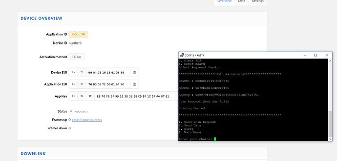
I’m using it on EU-868 band and it worked out of the box. I’d double check the config files for Device and Application EUI.
I’ve checked and double checked it, and it all seems good to me. ( see attached comparison between TTN console and the console of the board ). I edited lines
90 and 91 of conf_app. line 89, doe’stn change as the EUI is read from RAM. The only other thign i’ve edited is the symbols for the project, to turn off the frequencys that dont’ apply.
I’m stuck
/* OTAA Join Parameters */
#define DEMO_DEVICE_EUI {0xde, 0xaf, 0xfa, 0xce, 0xde, 0xaf, 0xfa, 0xce}
#define DEMO_APPLICATION_EUI { 0x70, 0xB3, 0xD5, 0x7E, 0xD0, 0x01, 0x6F, 0x90 }
#define DEMO_APPLICATION_KEY { 0xE8, 0x70, 0xFE, 0x5F, 0x99, 0x31, 0x3B, 0x36, 0xE8, 0xC5, 0xEF, 0x1C, 0x57, 0x4A, 0x87, 0x61 }
I got this from microchip support but am not quite sure I understand what they are asking.
- The setup is a RAK841 thats attached to TTN, so i assume that they are different nodes.
- How can I check to see if there is a JOIN request being made at the gateway or the server and if there was a MIC check failure?
Can you please confirm if your network server and gateway are same node or different nodes? Also can you confirm if you saw JOIN request at Gateway or Network Server? This would help in understanding the issue better. Normally the JOIN request is transparent to the gateway and it should just relay it to the Network Server.
The JOIN Request carries a MIC (Message Integrity Check) which is calculated using the APP Key. If the Network Server does not have the same APP Key, MIC check on Network Server will fail and it will send a Join Failure. To debug this further, we would need to know MIC check passed or failed on Network Server. Please advise if it is possible to get these logs.
If MIC check passed on Network Server, then it should send a Join response with success. If MIC check failed, then it should send a Join response with failure. Can you check if Network Server is generating the response?
If it is generating the response, then we would need to review the RX1 and RX2 settings at the device side to ensure they match the network expectations.
Hope that helps. Please let us know once you have this information.
I’m guessing you mean RAK831, I have the same setup.
Recently the ASF 3 has been updated, so as the example code itself. That might me the reason. I’m attaching my version of the project as a reference.
How can I check to see if there is a JOIN request being made at the gateway or the server and if there was a MIC check failure?
Normally, I can see all the join requests on TTN Console’s Traffic tab.
Let me know if it helps. Good luck.
https://www.dropbox.com/s/5a45ebtkpjhsf4o/SAMR34-LoRaWAN-Mote.zip?dl=0
Solved the problem. (doh). I needed to change the sub-band for 915Mhz operation to sub-band 2, which turned out to be a single change. Was a good learning exercise.
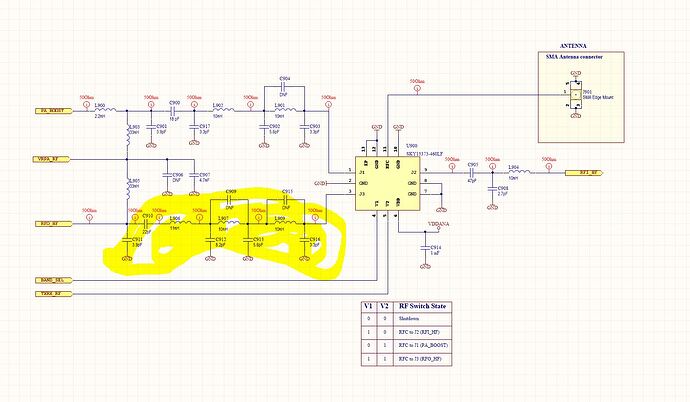
I’m looking at how to minimise the bom as best i can now, and it seems to me that i should be able to remove the filter components in the 868Mhz path… ( see rthe highlighted parts for removal )
Any thoughts?
You will need to replace these with similar components tuned to 915MHz.
The 915Mhz path is what is connected to port J1, so i was’tn planning on taking it out… The 868 port is whats on the side i marked off to remove. The RF switch chooses which side…
That’s interesting. I have a Dev Kit but not had the time to get it working. Learnt something very interesting. Thanks
Have a read of Microchip AN2842 page 12 which talks about the matching networks for 868 and 915… RF is blackmagic to me. I am a bit lost.
for regions with +14dBm max output power (868…), the PA_BOOST path is not needed.
for regions with +20dBm max output power (915…), the RFO path is not needed (but it is recommended because it is very efficient in low power transmissions).
in both cases you can save some bom cost removing pasives and changing SP3T to SPDT.
For a multi region design you need the 3 paths
I’m confused here… I thought The choice of path is is between a filter set for 868 and 915, not between if its using the PA, RFO.
the pasives values are almost the same for 868 and 915.
but yes, you can tune RFO pasives for 868 and PABOOST values for 915.
Hey guys.
I added all the project files to my Github (TinyLoRa). Please feel free to check it out. I’d really appreciate any feedback you guys can give on bugs and future improvements.
Cheers,
Orkhan.
Which board are you using ? Is it armmbed compatible ?
Do you have any code yet?
To do some basic testing I simply used the example codes from Atmel Studio (ASF v3.45).
Once you move past the basic examples ( which work quite well ) unorutanty things get pretty rough pretty quickly… The ASF wizard for the R34 is very incomplete. For example i’m just doing some work with generating some PWM. Its just not there. The workaround is to use some L21 code, but then you have to give up on ASF…
I’ve project code for LoRaMac-node and SAMR34 with Keil. But need found it from previous year. I’ll add to my github if found. If TinyLora owner can connect it via debugger to computer - i can debug over internet.
What type of plans / use cases do you have for this platform ? Your choice of feather form factor is a great selection.
One item you might consider is to allow controlling the power to the RF switch in the design.
today you have it directly connected to VDDA ( like the Microchip eval board ) but this RF switch will draw between 5 and 7 microamps by itself when the SAMR34 is in any of the deep sleep modes, so it is the controlling factor for ultra low power vs the modes of the SAMR34.
Since your breakout/feather board will also add extra currents, maybe this is not a problem for you. Just be aware of this added current. Maybe the power to this device could be carefully controlled by an IO pin.
Depending upon your region, a shield might be required over the module circuitry if it was to go thru regulatory certifications.
Will these be available assembled or semi assembled somewhere ( BGA is hard to handle)
K

