Are your sensor_address values correct? Why not try with 0x77?
The number represents the same value just in a binary format. I also use this code like that and its not an issue.
0b11101110 for me seems to be the same as 0xEE or should I read it right to left?
@jdelaet
You are right and made me insecure for a moment.  But then I remberd its a 7bit address followed by 0. So its 1110111 plus a 0. Thats why I wrote most of the sensor address in this format.
Without … I hope to try WITH in next one to two days…
However it also leads to this question…
Why was this fork created?
https://developer.mbed.org/teams/HereLab/code/BME280/
and might it ‘specifically’ assist us with this issue…
Could you take a look and give your thoughts…?
Thank you!
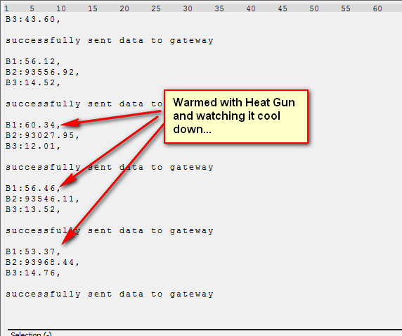
Tested BME280 WITH pullups and result is NO change (sorry to say)
I have tested with:
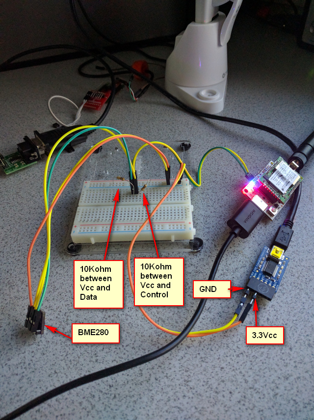
a) 10Kohm resistor between VCC and SDA
b) 10Kohm resistor between VCC and SCL
c) Used address 0x76
d) Found address using I2C_scanner mbed program
e) Set this for BME280 ONLY to remove any other ‘possible confilcts’
f) See the image below:

Any thoughts on this ‘setup’?
Sorry to hear that  .
.
The only thing I’ve seen in the other library you mentioned is that they are using directly 0x76 or 0x77. But you mentioned that you’ve tested that too.
I’ve seen that I’m using the" binary 7bit address plus" for MAX44009 and BME280 and the Hex Format for the others. It’s strange and truly not properly coded but it works.
I’ve to take a deeper look into my code the next days but at the moment I can’t imagine that something is wrong with it because it works perfectly with my Hardware. My I2C_RT should also be correct because it is used by all the other Sensors that work on your Hardware too.
@Halfbrain Its WORKING!!!

Here is the solution:
a) 10Kohm resistors across SDL and SCK
b) Use this value for the address
'#define BME280_SENSOR_ADDRESS 0b11101100 /**< Sensor address */
Done!
Thank you so much for through this with me… Niceeeeeeeeeeeeeeeeeeeeeeeeeeeeeeeeee!
In summary EVERYTHING is working correctly with the exception of sending packets to TTN as ASCII instead of Binary… Let me know when you think you will be able to ‘tackle’ that… Thanks again for all!
So glad we could solve that 
So you are using the standard adress 0b11101100 (0x76) and just mounted the pull ups? Does the diymall and adafruit sensor work?
a) Yes, using ‘0b11101100’ and mounted the pullups
NOTE: (0x76) is the value that I reported, last night, did NOT work…
It was only this morning when I realized, so I changed it to the binary value and it does work
b) Diymal is working … for this Success… I will wire up Adafruit tonight and provide to you the results…
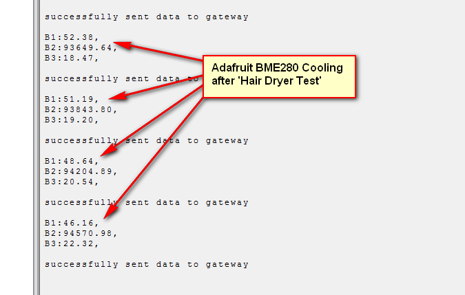
@Halfbrain Good News to report… Adafruit BME280 Works with Sensornode program
a) Using 10Kohm Resistors pullups on both SDA and SCL
and
b) using binary address: ‘0b11101110’
See image: Cooling from ‘Hair Dryer Test’

I think now you can update your Wiki for BME280 with these results. They should solve others need to connect BME280’s… Thank you…
Happy to annouce you that my Firmware is now able to
 receive and process Downlink Messages.
More infos on how to use it can be found on my Wiki LoRa Downlink Messages Page I wrote.
If you have some Questions or Feedback don’t hesitate to post it in this thread.
Need help to debug… using mdot and custom channel lib
[details=Summary]#include “mbed.h”
#include “mDot.h”
#include “MTSLog.h”
#include
#include
#include
#include “mbed.h”
#include “parse_keys.h”
#include “CustomChannelPlan_KR920.h”
#define BUILTIN_LED_ON 0
#define BUILTIN_LED_OFF 1
static const char APP_EUI[] = “BE7A000000000393”;
static const char APP_KEY[] = “3FE0040E234141A08A583D5F508B5781”;
Serial debug(USBTX, USBRX);
static mDot* dot;
// so we have some state
static uint16_t counter = 0; // always persisted to non-volatile mem
static bool woke_from_interrupt = false;
static InterruptIn btn(PA_1); /* D6 /
static DigitalOut led(PC_13, BUILTIN_LED_OFF); / D2 */
static void read_counter() {
char buffer[2];
bool res = dot->readUserFile(“counter”, &buffer, 2);
if (res) {
counter = (buffer[0] << 8) + buffer[1];
}
else {
counter = 0;
}
}
static void up_counter() {
logInfo(“up counter”);
read_counter();

counter++;

char buffer[2];
buffer[0] = counter >> 8 & 0xff;
buffer[1] = counter & 0xff;

logInfo("new counter value is: %d", counter);

dot->saveUserFile("counter", &buffer, 2);
}
static void btn_rise() {
woke_from_interrupt = true; // will be woken by STM32
}
static bool send_data(void) {
int32_t ret;
// check join state, @todo: add a timeout here, join is very expensive on the battery...
if (!dot->getNetworkJoinStatus()) {
    logInfo("trying to send before joining, retry join...");
    if ((ret = dot->joinNetwork()) != mDot::MDOT_OK ) {
        logError("failed to join network %d:%s", ret, mDot::getReturnCodeString(ret).c_str());
        return false;
    }
    else {
        logInfo("joined network successfully");
    }
}

std::vector<uint8_t> data;
data.push_back(counter >> 8 & 0xff);
data.push_back(counter & 0xff);

logInfo("sending %d bytes", data.size());
if ((ret = dot->send(data)) != mDot::MDOT_OK) {
    logError("failed to send %d:%s", ret, mDot::getReturnCodeString(ret).c_str());
    return false;
} else {
    logInfo("successfully sent data to gateway");

    std::vector<uint8_t> recv_data;
    if ((ret = dot->recv(recv_data)) != mDot::MDOT_OK) {
        logError("failed to recv %d:%s", ret, mDot::getReturnCodeString(ret).c_str());
        return true; // sending succeeded, just recv failed
    }

    if (recv_data.size() > 0) {
        printf("[INFO] received %d bytes:", recv_data.size());
        for (size_t ix = 0; ix < recv_data.size(); ix++) {
            printf(" %02x", recv_data[ix]);
        }
        printf("\r\n");

        if (recv_data[0] == 1) {
            led = BUILTIN_LED_ON;
        }
        else {
            led = BUILTIN_LED_OFF;
        }
    }

    return true;
}
}
static void wakeUpCallback() {
logInfo(“woke up, fromInterrupt=%d”, woke_from_interrupt);
bool wfi = woke_from_interrupt;

// if we were woken up by RTC_ALARM, first up the counter
if (wfi) {
    // reset the interrupt var
    woke_from_interrupt = false;

    up_counter();
}


bool sent = send_data();
// not sent? try again in 5 minutes...
if (!sent) {
    uint32_t sleep_time = 5 * 60;

    // if woke from button press, check duty cycle first...
    if (wfi) {
        // hmm.. something went wrong. Probably duty cycle, see next Tx frame
        // get the next transmission frame (in whole seconds)
        sleep_time = ceil(static_cast<float>(dot->getNextTxMs()) / 1000.0f);

        // Tx window open, but no success? Try again in 30s.
        if (sleep_time == 0) sleep_time = 30;
    }

    logInfo("Going back to sleep (RTC_ALARM), time=%d", sleep_time);
    dot->sleep(sleep_time, mDot::RTC_ALARM, false);
}
else {
    logInfo("Going back to sleep (INTERRUPT)");

    // go back to sleep (wait for an interrupt to happen)
    dot->sleep(0, mDot::INTERRUPT, false);
}
}
int main() {
debug.baud(9600);
int32_t ret;
printf(“Entering main()\r\n”);
btn.rise(&btn_rise);

// get a mDot handle
dot = mDot::getInstance();
// dot->setLogLevel(mts::MTSLog::DEBUG_LEVEL);
dot->setLogLevel(mts::MTSLog::TRACE_LEVEL);
// print library version information
logInfo("version: %s", dot->getId().c_str());

std::vector<uint8_t> devEui = dot->getDeviceId();
logInfo("device eui: %02x:%02x:%02x:%02x:%02x:%02x:%02x:%02x",
    devEui[0], devEui[1], devEui[2], devEui[3], devEui[4], devEui[5], devEui[6], devEui[7]);

lora::CustomChannelPlan_KR920* plan = new lora::CustomChannelPlan_KR920(*dot->getRadio(), *dot->getSettings());
dot->setChannelPlan(plan);

//*******************************************
// configuration
//*******************************************
// reset to default config so we know what state we're in
dot->resetConfig();

logInfo("frequencyBand: %d", dot->getFrequencyBand());

  logInfo("setting frequency sub band");
if ((ret = dot->setFrequencySubBand(1)) != mDot::MDOT_OK) {
    logError("failed to set frequency sub band %d:%s", ret, mDot::getReturnCodeString(ret).c_str());
}

// set up the mDot with our network information: frequency sub band, network name, and network password
// these can all be saved in NVM so they don't need to be set every time - see mDot::saveConfig()

logInfo("setting public network");
if ((ret = dot->setPublicNetwork(true)) != mDot::MDOT_OK) {
    logError("failed to set public network %d:%s", ret, mDot::getReturnCodeString(ret).c_str());
}


logInfo("setting tx power to 20");
if ((ret = dot->setTxPower(18)) != mDot::MDOT_OK) {
    logError("failed to set tx power %d:%s", ret, mDot::getReturnCodeString(ret).c_str());
}

logInfo("setting rx join freq");
if ((ret = dot->setJoinRx2Frequency(921900000)) != mDot::MDOT_OK) {
    logError("failed setting rx join freq %d:%s", ret, mDot::getReturnCodeString(ret).c_str());
}

logInfo("setting  join retry");
if ((ret = dot->setJoinRetries(5)) != mDot::MDOT_OK) {
    logError("failed setting  join retr %d:%s", ret, mDot::getReturnCodeString(ret).c_str());
}

logInfo("setting rx join dr");
if ((ret = dot->setJoinRx2DataRate(0)) != mDot::MDOT_OK) {
    logError("failed setting rx join dr %d:%s", ret, mDot::getReturnCodeString(ret).c_str());
}

// set up the network keys
ParseKeys::initializeOta(dot, APP_EUI, APP_KEY);

// a higher spreading factor allows for longer range but lower throughput
// in the 915 (US) frequency band, spreading factors 7 - 10 are available
// in the 868 (EU) frequency band, spreading factors 7 - 12 are available
logInfo("setting TX spreading factor");
//if ((ret = dot->setTxDataRate(mDot::SF_9)) != mDot::MDOT_OK) {
if ((ret = dot->setTxDataRate(mDot::DR5)) != mDot::MDOT_OK) {
    logError("failed to set TX datarate %d:%s", ret, mDot::getReturnCodeString(ret).c_str());
}

// request receive confirmation of packets from the gateway
logInfo("enabling ACKs");
if ((ret = dot->setAck(1)) != mDot::MDOT_OK) {
    logError("failed to enable ACKs %d:%s", ret, mDot::getReturnCodeString(ret).c_str());
}

logInfo("enabling ADR");
if ((ret = dot->setAdr(1)) != mDot::MDOT_OK) {
    logError("failed to enable ADR %d:%s", ret, mDot::getReturnCodeString(ret).c_str());
}

// save this configuration to the mDot's NVM
logInfo("saving config");
if (! dot->saveConfig()) {
    logError("failed to save configuration");
}

// OTA JOIN sequence, remove when using personalized mode
logInfo("joining network");
if ((ret = dot->joinNetwork()) != mDot::MDOT_OK ) {
    logError("failed to join network %d:%s", ret, mDot::getReturnCodeString(ret).c_str());
}
else {
    logInfo("joined network successfully");
}

//*******************************************
// end of configuration
//*******************************************
// read_counter();
//dot->setWakeupCallback(&wakeUpCallback);
// dot->sleep(0, mDot::INTERRUPT, false);
// while (true) {
// wait_ms(1000);
// }
}
[/details]
Hi shmrymbd,
Whats your question? You aren’t using my the firmware i’ve written?
hi. i need a custom channel… for as920-923 channeling. so i dont know which code is good to start with. thansk anyway for the reply
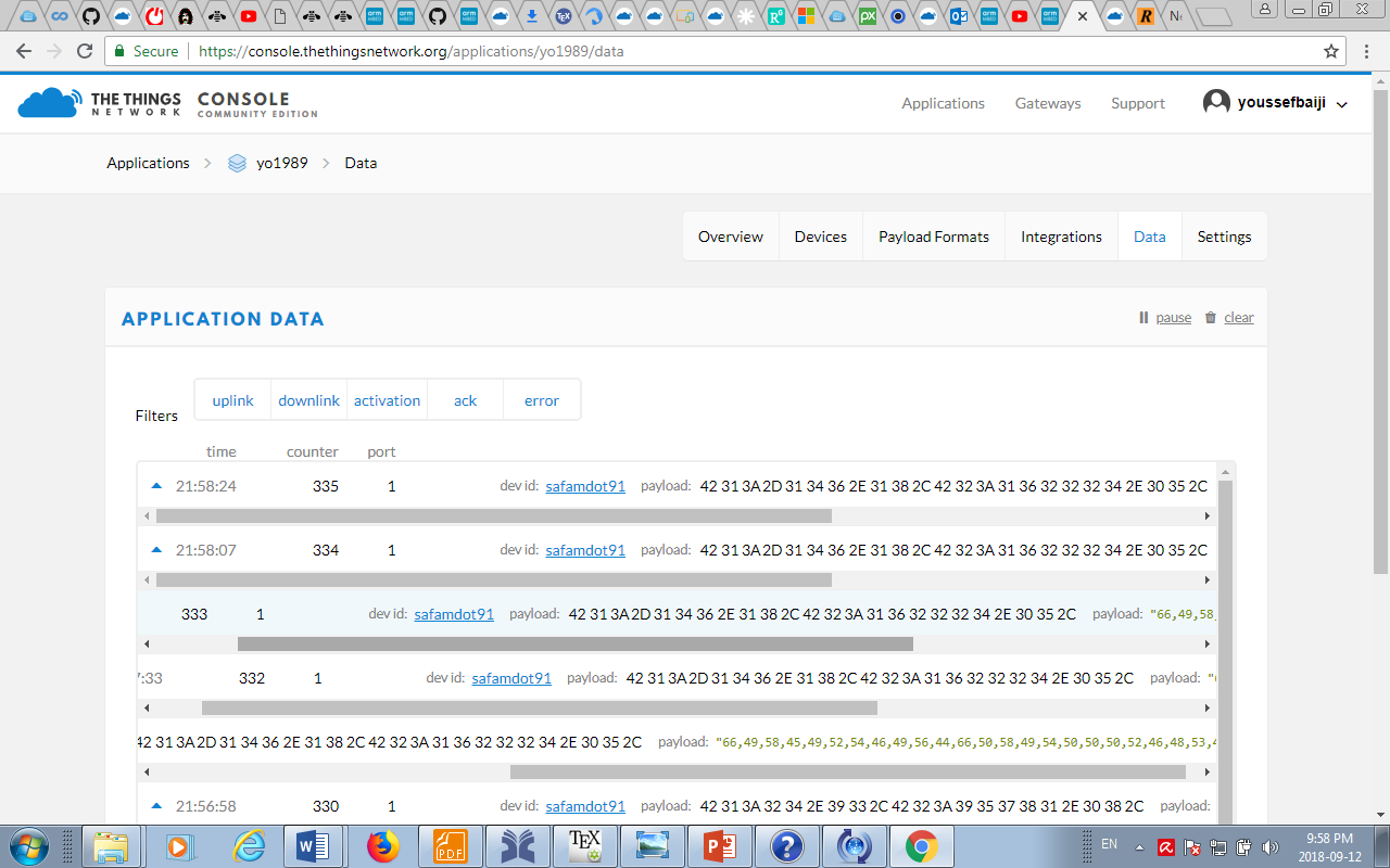
Hello man i used you code ,im using Bme 280 to gather pressure temp this what i get it doesnt make sense right?

Hi. Glad you are using it. Your data seems legit. These are the hex values you see. For example 42 31 3A is B 1 : .
To get a human readable format i suggest you to log into your ttn console then in your application go to payloadformats and under decoder you enter this code part:
function Decoder(bytes) {
var result="";
for (var i = 0; i < bytes.length; i++) {
result += String.fromCharCode(parseInt(bytes[i]));
}
return {
payload: result,
};
}
This will decode the hex values in to ascii and you will be able to read the payload.
If any further questions don’t hesitate to ask.
you are really helpful thanks ,am doing research after i gather data am going to use it and do some machine learning am kind of lost so i might ask you questions along the way ,thank you very much
so B1 is temp and B 2 is pressure?