ah ok, I thought that blackberry keyboard was very expensive.
complicated project… how’s the firmware going ?
q10 bb kb are only 4 USD but the hirose 28 pin nano connector is awfull.
firmware is the one of ESP32 dev board.
I have mst of thel the functions in C done.
just need to assemble the puzzle’s pièces.
looking good ! 
Hi, is there any update on this project? There is an agricultural use case for this here in Ireland. Thanks. Albert.
What’s the status today? Remembering 5 months later?
Finally you did it with touch screen which is great! Buttons sucks )
Yes. I will work on the Q10 keyboard part but later. I need to add another microcontroler for the keyboard only.
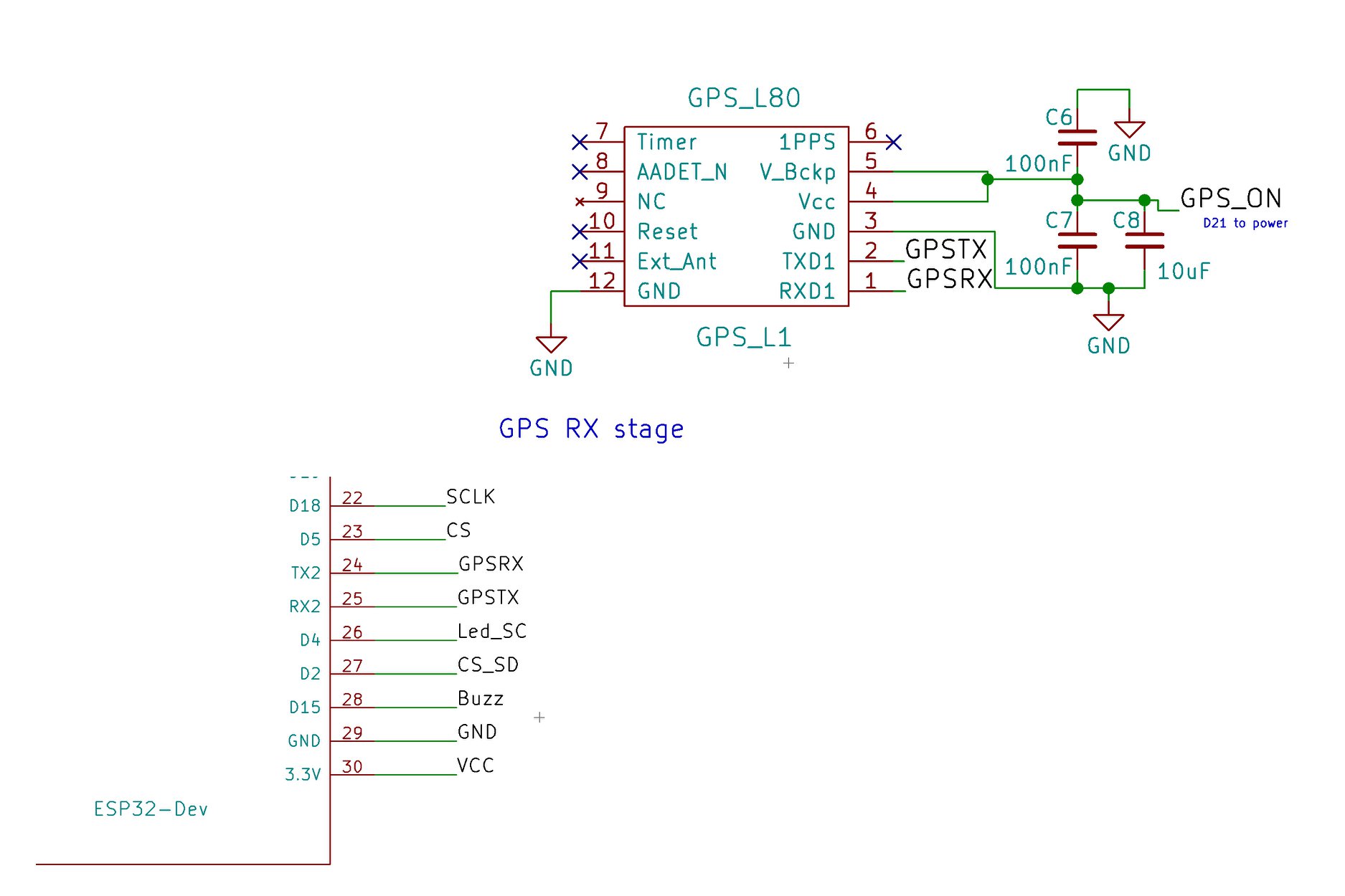
Now fighting with the GPS from QUECTEL L80-R connected to TX2 RX2 of a DOIT ESP32 DEV BOARD. And TinyGPS++ arduino library. My first time with GPS. I’m a bit lost. Impossible to get information from the GPS module YET. All the other functions are working well. Now making the software, designing the graphic menus …
What do you mean by ‘impossible to get information’? Usually GPS module sends lots of data when it is connected. If not then may be you have problem with satellite signal or interface?
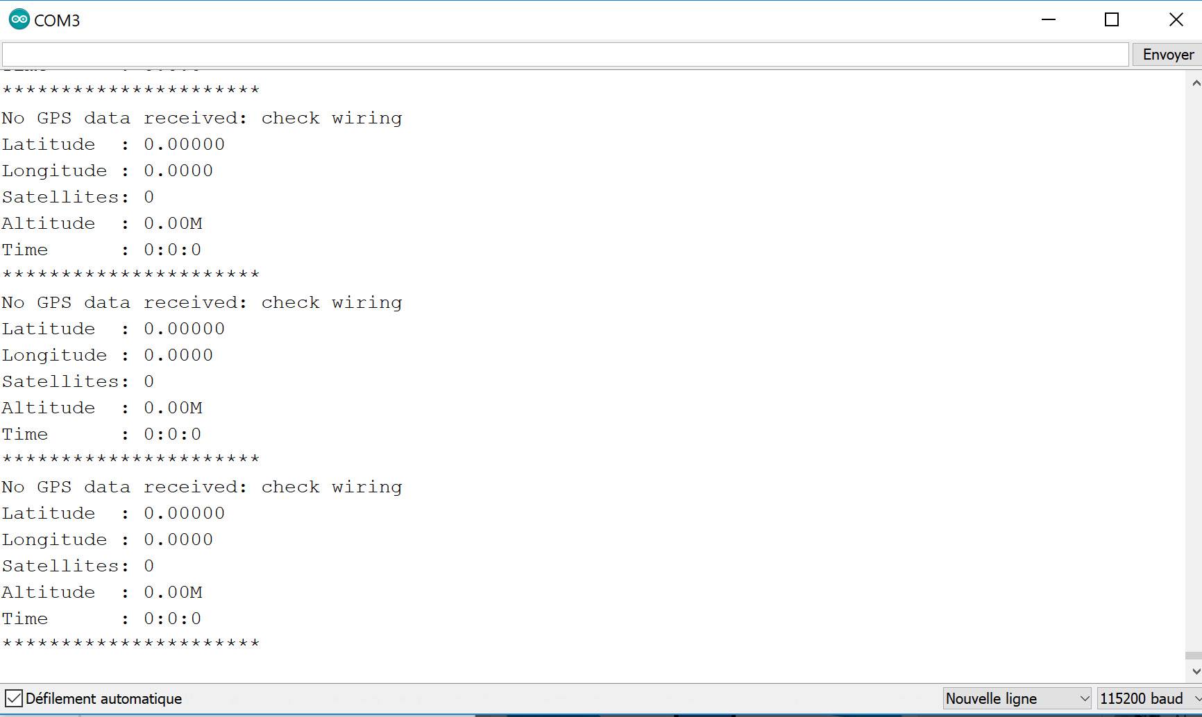
This is the first time I deal with GPS module. I’m becoming mad with such a simple thing … I cannot get any informations out. I’m probably doing something silly because I’m not used to .
After 5 minutes under the satellite. Nothing on UART2 RX from the GPS module


#include <TinyGPS++.h>
TinyGPSPlus gps;
HardwareSerial Serial1(1);
void setup()
{
// Setup GPS ON PIN 21
pinMode(21, OUTPUT); // sets the digital pin 13 as output
digitalWrite(21, HIGH);
delay(1000);
Serial.begin(115200);
Serial1.begin(9600, SERIAL_8N1, 17, 16);
}
void loop()
{
Serial.print("Latitude : ");
Serial.println(gps.location.lat(), 5);
Serial.print("Longitude : ");
Serial.println(gps.location.lng(), 4);
Serial.print(“Satellites: “);
Serial.println(gps.satellites.value());
Serial.print(“Altitude : “);
Serial.print(gps.altitude.feet() / 3.2808);
Serial.println(“M”);
Serial.print(“Time : “);
Serial.print(gps.time.hour());
Serial.print(”:”);
Serial.print(gps.time.minute());
Serial.print(”:”);
Serial.println(gps.time.second());
Serial.println(”**********************”);
smartDelay(1000);
if (millis() > 5000 && gps.charsProcessed() < 10)
Serial.println(F(“No GPS data received: check wiring”));
}
static void smartDelay(unsigned long ms)
{
unsigned long start = millis();
do
{
while (Serial1.available())
gps.encode(Serial1.read());
} while (millis() - start < ms);
}
I also had much trouble.
One issue was I wired the GPS to normal serial when it only worked reliably using 3.3v TTL… I was getting bad sentences, so my lora decode was presenting gibberish. I bashed away for days before I gave up and tried to just display the raw feed from the GPS, and realized it was bad. I used a TTL 3.3v usb adaptor to connect directly to the GPS, and saw that it was good, it was just how I had it connected - .
I was using a Wemos D1 Mini (ESP 8266) like you.
My suggestion is bypass the Arduino, until you get data from the GPS directly to Putty on PC using USB TTL. If your GPS won’t send data to a PC, it’s not going to work with the Arduino…
Try something like this. https://core-electronics.com.au/usb-to-ttl-serial-uart-rs232-adaptor-pl2303hx.html
I’ve spent ages on GPS nmea feeds at 4200 (standard speed), I might be able to help more.
Hi ccadic! This is a very nice project, and I’m really impressed with the hardware that you managed to put together!
I’m curious about what you’ve managed to accomplish on the protocol side? Is there any code, or even some sort of template/outline that you’ve been working on regarding how the network would operate?
It would be interesting to have something that works on your platform, but would also would also work on an off-the-shelf esp32-lora-oled module tied to a phone via bluetooth.
Tnx for the Kong’Grats 
I’m presently coding (arduino IDE) the main functions of the board. A lot of code is not yet written( I’m not too good at coding in arduino IDE)
I planed to use a MESH protocole
/***************************************************
  This is our GFX example for the Adafruit ILI9341 Breakout and Shield
  ----> http://www.adafruit.com/products/1651

  Check out the links above for our tutorials and wiring diagrams
  These displays use SPI to communicate, 4 or 5 pins are required to
  interface (RST is optional)
  Adafruit invests time and resources providing this open source code,
  please support Adafruit and open-source hardware by purchasing
  products from Adafruit!

  Written by Limor Fried/Ladyada for Adafruit Industries.
  MIT license, all text above must be included in any redistribution
 ****************************************************/
#include "SPI.h"
#include "Adafruit_GFX.h"
#include "Adafruit_ILI9341.h"

#include <LoRa.h>    // this is the one by Sandeep Mistry
#include "FastLED.h"

#define _cs   12   // 3 goes to TFT CS
#define _dc   27   // 4 goes to TFT DC
#define _mosi 23  // 5 goes to TFT MOSI
#define _sclk 18  // 6 goes to TFT SCK/CLK
#define _rst  13  // ESP RST to TFT RESET
#define _miso     // Not connected
//       3.3V     // Goes to TFT LED
//       5v       // Goes to TFT Vcc
//       Gnd      // Goes to TFT Gnd

// LoRa Settings
#define BAND 868500000.00
#define spreadingFactor 9
// #define SignalBandwidth 62.5E3
#define SignalBandwidth 31.25E3
#define codingRateDenominator 8
#define preambleLength 8

// SPI RFM95 PINS
//SPI defs for screen
#define SS 5
#define RST 14
#define DI0 26

// Buzzer information
int channel         = 0;
int frequence       = 2000;
int resolution      = 10;
unsigned long timer = millis();
int buzzer_pin = 15;

TaskHandle_t dobitaobyte;
eTaskState statusOf;


//LEDS
// SNAPONAIR RGB LED TEST CODE
#define NUM_LEDS 1
#define DATA_PIN 22
#define BRIGHTNESS  40  // From 0 to 255

CRGB leds[NUM_LEDS];

// misc vars
String msg;
String displayName;
String sendMsg;
char chr;
int i=0;


// Use hardware SPI (on ESP D4 and D8 as above)
//Adafruit_ILI9341 tft = Adafruit_ILI9341(_CS, _DC);
// If using the breakout, change pins as desired
Adafruit_ILI9341 tft = Adafruit_ILI9341(_cs, _dc, _mosi, _sclk, _rst);

void setup() {
  Serial.begin(115200);
  Serial.println("ILI9341 Test!");

  // Set LEDS
      FastLED.addLeds<NEOPIXEL, DATA_PIN>(leds, NUM_LEDS);
      LEDS.setBrightness(BRIGHTNESS);

  // Setup GPIO4 on
  pinMode(4, OUTPUT);          // sets the digital pin 4 as output to power the backgrnd led
  digitalWrite(4, HIGH);

  tft.begin();
  // read diagnostics (optional but can help debug problems)
  uint8_t x = tft.readcommand8(ILI9341_RDMODE);
  Serial.print("Display Power Mode: 0x"); Serial.println(x, HEX);
  x = tft.readcommand8(ILI9341_RDMADCTL);
  Serial.print("MADCTL Mode: 0x"); Serial.println(x, HEX);
  x = tft.readcommand8(ILI9341_RDPIXFMT);
  Serial.print("Pixel Format: 0x"); Serial.println(x, HEX);
  x = tft.readcommand8(ILI9341_RDIMGFMT);
  Serial.print("Image Format: 0x"); Serial.println(x, HEX);
  x = tft.readcommand8(ILI9341_RDSELFDIAG);
  Serial.print("Self Diagnostic: 0x"); Serial.println(x, HEX);


// We set the ID of the pager
 displayName = "SoA001";

tft.setRotation(3);
testText();

tft.setRotation(3);
delay(1000);
testText();
delay(1000);
/*
// Send packet
     msg="First txt message in chat";
// Receive a message first...
      sendMsg += displayName;
      sendMsg += msg;
      // send message
      LoRa.beginPacket();
      LoRa.print(sendMsg);
      LoRa.endPacket();

      Serial.println(sendMsg);
    //  tft.setTextColor(ILI9341_RED);  tft.setTextSize(1);
    //  tft.println(sendMsg);
      // clear the strings and start again :D
      msg = "";
      sendMsg = "";

*/


}


void loop(void) {

// tft.setRotation(3);
//  testText();
//   delay(1000);
}


unsigned long testText() {

  tft.fillScreen(ILI9341_BLACK);

 // Draw the screen cells
  tft.drawRect(1,1, 319, 239, ILI9341_RED);
// First line separator
  tft.drawLine( 1, 20, 319, 20, ILI9341_RED);
// 2nd line separator
  tft.drawLine( 1, 40, 319, 40, ILI9341_RED);
// keyboard line 1
tft.drawLine( 1, 239-(5*20), 319, 239-(5*20), ILI9341_RED);
  tft.drawLine( 1, 239-(4*20), 319, 239-(4*20), ILI9341_RED);
  tft.drawLine( 1, 239-(3*20), 319, 239-(3*20), ILI9341_RED);
   tft.drawLine( 1, 239-(2*20), 319, 239-(2*20), ILI9341_RED);
    tft.drawLine( 1, 239-(1*20), 319, 239-(1*20), ILI9341_RED);
// kb first line
  tft.setCursor(6, 245-(5*20));
  tft.setTextColor(ILI9341_WHITE);  tft.setTextSize(1);
  tft.print("~   1   2   3   4   5   6   7   8   9   _   =   Bksp");
// kb 2nd line
  tft.setCursor(6, 245-(4*20));
  tft.setTextColor(ILI9341_WHITE);  tft.setTextSize(1);
  tft.print("   Q   W   E   R   T   Y   U   I   O   P   [   ]");

// kb 3RD line
  tft.setCursor(6, 245-(3*20));
  tft.setTextColor(ILI9341_WHITE);  tft.setTextSize(1);
  tft.print("Tab   A   S   D   F   G   H   J   K   L   ;   '  Ent");

 // kb 4th line
  tft.setCursor(6, 245-(2*20));
  tft.setTextColor(ILI9341_WHITE);  tft.setTextSize(1);
  tft.print("Shift   Z   X   C   V   N   B   N   M   ,   .   /");

// kb (th line
  tft.setCursor(6, 245-(1*20));
  tft.setTextColor(ILI9341_WHITE);  tft.setTextSize(1);
  tft.print(" Ctrl  Alt            <SPACE>");
// Separation
 for(int x = 0; x < 12; x++){
    tft.drawLine( 24*x+20, 239-(5*20), 24*x+20, 239-(4*20), ILI9341_RED);
  }

 for(int x = 0; x < 13; x++){
    tft.drawLine( 24*x+15, 239-(4*20), 24*x+15, 239-(3*20), ILI9341_RED);
  }


 for(int x = 0; x < 12; x++){
    tft.drawLine( 24*x+32, 239-(3*20), 24*x+32, 239-(2*20), ILI9341_RED);
  }
 for(int x = 0; x < 12; x++){
    tft.drawLine( 24*x+45, 239-(2*20), 24*x+45, 239-(1*20), ILI9341_RED);
  }
 for(int x = 0; x < 2; x++){
    tft.drawLine( 34*x+40, 239-(1*20), 34*x+40, 239, ILI9341_RED);
  }
 tft.drawLine( 34*6+40, 239-(1*20), 34*6+40, 239, ILI9341_RED);

  unsigned long start = micros();
  tft.setCursor(6, 8);
  tft.setTextColor(ILI9341_RED);  tft.setTextSize(1);
  tft.println("www.SnapOnAir.com");

  // print GPS coordinates
  tft.setCursor(6, 28);
  tft.setTextColor(ILI9341_RED);  tft.setTextSize(1);
  tft.print("GPS:");
  tft.setTextColor(ILI9341_WHITE);  tft.setTextSize(1); // 47.86944,1.837931000000026
  tft.print("47.86944,1.837931000000026   ");
  tft.setTextColor(ILI9341_RED);  tft.setTextSize(1);
  tft.print("Freq:");
  tft.setTextColor(ILI9341_WHITE);  tft.setTextSize(1);
  tft.println("868.500 Mhz");

  // SET LED
  SetRGBLED(5);

  // delay so you have time to
   delay(1000);

  // Turn the LED OFF
  SetRGBLEDOFF();

  return micros() - start;
}


int SetRGBLEDOFF(){

  // Turn off LED
    leds[0] = CRGB::Black;
    FastLED.show();
}


int SetRGBLED(int ledcolor){
    if (ledcolor == 1) {
    // turn LED on BLUE:
    leds[0] = CRGB::Blue;
    }

    if (ledcolor == 2) {
    // turn LED on : Yellow
    leds[0] = CRGB::Yellow;
    }

     if (ledcolor == 3) {
    // turn LED on RED:
    leds[0] = CRGB::Red;
    }

     if (ledcolor == 4) {
    // turn LED on ORANGE:
    leds[0] = CRGB::Orange;
    }

     if (ledcolor == 5) {
    // turn LED on Pink:
    leds[0] = CRGB::Pink;
    }


   FastLED.show();
}


// Buzzer Function
void sirene(void *pvParameters){
    float sinVal;
    int   toneVal;
    for (byte t = 0; t<10;t++){
        for (byte x=0;x<180;x++){
            //converte graus em radianos
            sinVal = (sin(x*(3.1412/180)));
            //agora gera uma frequencia
            toneVal = 2000+(int(sinVal*100));
            //toca o valor no buzzer
            ledcWriteTone(channel,toneVal);
            //Serial.print("*");
            //atraso de 2ms e gera novo tom
            delay(4);
        }
    }
    ledcWriteTone(channel, 0);
    vTaskDelete(NULL);
}pls FORMAT your code
to avoid very long code and txt
example:
Click to see the full logs
This text will be hidden,
until clicked
…which will get you:
Click to see my full logs

Yes. I will. When finished. I prefer focusing on the code to work rather than cosmetic presentation 
ok… have it your way, irritating long post deleted
This is not about formatting your code in the programming environment, it is about formatting your message on the forum. As courtesy for the forum users you should insert two lines to format your message. Or is that too much to ask?
Just insert [code] before you code and [/code] after.
As the code is interesting I reformatted and restored it.
sorry. I’m new with these options :))) I’ll try not to make any mistake next time
english please 