ah ok, I searched for CXL 900-3LW and found 3 different types… but there are more 
@Epyon, you mentioned using an isolated power supply to complement a grounded antenna cable. Do you have any pointers on where to get those isolated power supplies? I’m having a bit of trouble finding them, at least in versions that are properly sealed off, with a standard 230V connector (as opposed to screw terminals for the 230V connection).
would an old pc power supply do?
These isolated power supplies are mostly industrial. I always uses DIN rail mounted PSU’s with screw connections, e.g. Phoenix Contact (cheap and reliable). I don’t know if you can find isolated wall wart supplies, which is probably what you are looking for. You need to have some distance between certain components to prevent sparking over during a fault condition, so this probably won’t fit in wall warts.
Maybe look for lighting transformers? These are sometimes isolated. I remember that my IKEA bathroom ledstrips use an isolated power supply (“Ansluta”).
Many articles books and standards have been written on lightning protection. But even if you do it next to perfect if will still disrupt services. See http://stichting-vitaalpendrecht.nl/2014/05/10/blikseminslag-in-toren-waalhaven-in-beeld/ which took out local Radio broadcasting and 3G/4G service showing once again that it’s next to impossible to protect fully against a massive direct hit. However you can minimize collateral damage. Implementing lightning protection can get quite expensive but you can learn from the principles, see what’s done by professionals and then see what’s doable for yourself.
The mantra in lightning protecting is grounding, grounding and…grounding. But ground properly.
So start with an Antenna with an internal DC short and mount it on a pole which is thoroughly grounded with >= 25 mm2 wiring. Of the Antenna’s mentioned above only the Procomm has this short. Now the Procomm is a bit costly but it’s perfectly possible to make something yourself which has a DC short. The Rothammel Antennenbuch has plenty of ideas and even a folded dipole with a 1:4 balun can be grounded in the middle to meet the DC short requirement.
Another alternative is the “fietspomp” antenna which is a half lambda radiator fed by a quarter lambda stub, open on the top to match the radiator, shorted at the bottom. Impedance matching is done by tapping on the quarter lambda stub at the 50 Ohm point
Next is grounding the Coax cable. That usually only get’s done for long run’s with a maximum distance of 20 m between grounding collars.
After this when you need to go inside a building put an Over Voltage Protector outside at the building border and ground it with a cable kept running along the outside of the building.
Huber & Suhner makes real nice Over Voltage Protectors but they are not cheap. Count on 200 Euro’s minimum, see http://literature.hubersuhner.com/Technologies/Radiofrequency/Lightningprotection/?Page=66 Now the LORA band is very close to a cellular band so you might find something usable on E-bay. If you have the choice pick one based on the pure quarter wave principle The ones with a gas discharge tube are second choice since:
- They have a higher rest voltage;
- If you suspect it has handled a strike the gas discharge tube should be replaced. (Nobody does
 ).
).
But also here a bit of mechanical ingenuity can save money. A shorted quarter wave piece of good coax like RG214 or 1/2" Cellflex in parallel to the Coax feed line and properly grounded works just as well. Make sure to take the velocity factor of the cable into account and keep the cable grounding this device at the short also outside the building.
Now if you want to keep the Gateway outside, an Antenna with a DC short to ground, fiber optics data line and an isolated power supply is a good way of doing things. (Look closely at a cellular site, that’s exactly what they do!)
rgds
Pim
No it won’t work for our North American frequency of 915 MHZ.
This antenna is for the European Lora at 868 MHZ.
during performing reppeatitive tests that I’ve done , the longest communication distance with lora evaluation kit 868 MHZ was 600 meters,how is it possible to make it longer?
Without knowing any details on your tests only generic answers are possible, so here they are:
- Use a better antenna on the gateway
- Put the gateway antenna in a better location
I got the sunhans antenna but I don’t have time to test with it. Is anyone interested?
We have that Sunhans antenne on our first floor of our campus and it performs well, as uptil now…
I receive Lora beacons transmitted from Mechelen to Leuven, i.e. 30km wit SNR +/- -5 with standard TX power of 14dBm from a pole on 30m AGL. Our gateway is about 20m outdoor.
No probs !
I received mine too, still waiting on a pigtail for the N connector tho. Gonna start testing in Ghent in a week or so.
A little bit off-topic but it’s a outdoor antenna 
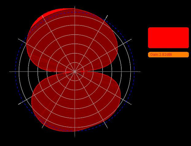
I’m still a bit confused on how to interpret the radiation pattern of the Sunhans antenna.

Because of the high gain it should be a collinear dipole array, but the the radiation pattern is more like a simple half-wave dipole turned 90°. I’m also not sure how to interpret the directivity that is claimed to be “V:55/30”  . Any antenna experts here?
I’m not an antenna expert but logical thinking get’s you a long way.
It’s a 2 band antenna: 790-960/1710-2700 MHz.
Look at how it’s specified. The / character is in the frequency range, bandwidth and the half power beam-width numbers.
That leads me to conclude that the 55 in the 55/30 is the quoted -3 dB beam width in degrees in the vertical plane for the 790-960 MHz freq. range. The 30 is the same parameter for the 1710-2700 MHz freq. range.
Now that does not tie up whatsoever with the depicted plot which could indeed be from a horizontal dipole with some conducting objects in it’s neighborhood changing it’s radiation pattern.
Note that there are no scales in this plot and the 2,81 dBi is a bit more then the theoretical gain of a dipole of 2,15 dBi.
A truly omni directional antenna in the horizontal plane with the gain listed must have a quite small vertical 3 dB half power beam width angle. Gut feeling (always dangerous but not to be ignored) tells me that for this quoted gain it must be smaller then the listed numbers and something does not match up here.
Also the pictures of the mounting bracket in relation to the antenna are  Mounting it that way will surely not make it omni-directional. Granted the mechanical drawings are correct:
For comparison on how to properly specify an antenna have a look at: https://www.kathreinusa.com/wp-content/uploads/2016/04/84010250.pdf
It’s for the American ISM band but notice what gain they quote, the radiation pattern and the non-ambiguity in their information. There is one drawback: high quality in performance, life time and specifications all come with a higher price…
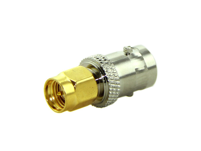
I’m contemplating this antenna for my TTN Gateway. If I’m not mistaken, I need a SMA-male adapter on the gateway side. From what I can read online, there is a BNC connector coming from the antenna. Can anyone point me to the right adapter? I can see adapters in the range of 2 to 45 Euros, and I’m not quite sure how and what to pick.
Not sure this is obvious out-of-thread: I mean the Conrad Aurel GP868
for readers and future antenna questions…
https://www.thethingsnetwork.org/forum/t/the-big-antenna-topic-part-1/7880
On first sight this looked like the 45 Euro one. Man, you scared me.  Thanks for the link!

