Regarding the gap of 16,384 messages…
That means that i can not transmit more than 16,384 messages?
No. It means at least one in every 16384 messages must be received and forwarded to the backend. If the last message processed by the backend differs too much from the counter in new messages the new message will be ignored.
Ok, but I don’t really understand it now. Can you explain that in more detail using an example?
Short explanation:
If TTN receives an uplink packet with counter 100, it must receive another uplink before the counter reaches 16485 (last counter value + 16384 + 1). Packets with counter values > 16484 will be ignored by TTN in line with requirements in LoRaWAN standard.
BTW: Perhaps you could take a look at the LoRaWAN standard document? That is where we get our information as well…
Thank you for information and for your hints!
In this case i want to check the status byte from RN2483 every hour. Bit number 4 shows the Join status (‘0’ – network not joined, ‘1’ – network joined).
But here i got another strange problem - if i implement this in my code, suddenly on microcontroller side the RX-Interrupt will not be triggered anymore.
And this has to do (so i am sure) with the RN2483 sleep mode, because it works when the module is not in sleep mode.
But for this problem i posted a separate threat here:
For future readers: that’s unlikely to ever change from “joined” to “not joined”, like has been discussed elsewhere.
If i understood right, when i save with command mac save after every unconfirmed or confirmed transmission i don`t need a rejoin OTAA.
But what if i have to reset my software and in this case i reset the RN2483A modul?
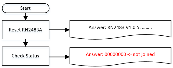
If i do that, after restart i check the status and it shows 00 00 00 00 - that means not joined.
If i don’t need a new re-join why do i get the answer 00000000 when i check the RN2483A status register after a restart of the MCU?

Do I write you do not need to rejoin in that message?
After a reset of the RN2483 module you will need to rejoin. However if you saved everything after the last transmit, you can use ABP join which basically initialized the LoRaWAN stack within the module without transmitting/receiving.
If the code on the main controller does not reset the RN module when the main controller is reset you do not need to rejoin. However in a lot of cases the main controller will be reset by removing and reapplying the power of the node and that will reset the RN module as well.
OK I have a question to this. If I store the session secrets. Disconnect the power f.e. Some days from my module and restore the secrets. Can I send when new uplink without rejoin?
Hi Jac,
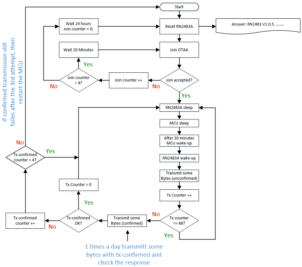
this is now my concept to make a robust communication on nodes side. After the join OTAA process and if join accepted, i send some bytes every 30 minutes with unconfirmed message. One times a day, i will send some bytes with confirmed message. If respond is ok, then repeat with unconfirmed message. If respond is not ok (after the 3rd try), restart the MCU.
Do you think this procedure is ok?
Here the flow-chart:

I would use the 48th data transmission for ack, not an additional transmission.
LoRaWAN confirmed uplinks probably don’t actually do what you want.
First, if you are using ADR (which is almost a given with OTAA) then the ADR state machine itself gives you some idea of confirmed connectivity.
Next, the confirmed message scheme is badly thought out - if you’re going to use it, then at least modify the node to never retransmit on failure, instead make the next ordinary message confirmed as well. That’s because if it’s the downlink side of the confirmation that fails, then no matter how many times you re-transmit the uplink, you will never get a confirmation for that re-used frame count.
But ultimately, what do you hope to accomplish in the case of failure - how is resetting the MCU going to fix anything?
In my case, i have not yet used ADR.
What I want to achieve is a stable connection. At least and this is important if a node cannot connect to the gateway for whatever reason. Maybe a problem with the software or the RN2483A module. Then the system should be able to reset itself and restart.
But human errors aside, what problems would be fixed by getting new secrets?
Your flow-chart is not trying to fix the reception quality (like by decreasing the data rate, like ADR would do). Also, it’s trying to get new secrets at a time when it knows something is wrong. Why would the OTAA Join succeed when the confirmed uplink failed? (Again, human errors aside.)
If TTN does not lose my keys (worst case) and when restoring after a possible reset of the RN2483A the keys saved with mac save are not lost, there is actually no reason to assume why data transmission should fail. Am I correct?
And If i understood right and i would use join ABP after a reset, i have to save after each and every transmission?
In my application I want to transmit 11 bytes, let’s say every hour and I use
radio pwr = 15
SF = 11
dcycle = 0,1%
DR = 5
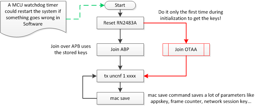
In this situation, I assume that the following flow chart could be the right solution?

It could very well still fail. It’s radio after all: even if the transmission is okay, it might collide with transmissions from other LoRa-devices or it might not be received by any operational TTN gateway. And even if received, the gateway might not be connected to the internet, the network servers might be down, and so on, and so on. But: such failure would not be caused by some mismatch in the secret keys, so would not be fixed by a new OTAA Join. (If such join would even succeed at that point in time.)
Your last flow seems to be the standard flow for an RN2483, I think. In Arduino terminology, the reset, configuration, Join OTAA and the first Recent RN2483 devices should support mac save would be in some setup(), and the Join ABP and subsequent mac save would be part of some measure-transmit-sleep loop(). So: the arrow after mac save should probably go to some sleep, and then go to Join ABP rather than to tx uncnf. I’m sure there are many OTAA examples for RN2483 (including many bad examples…).sys sleep rather than completely powering off the device, not requiring the mac save and mac join abp in some measure-transmit-sleep loop(). And beware:
Your example settings, showing SF11, require ADR as it’s not allowed to use a fixed SF11 or SF12. Also, you’ll save quite some time on air, and hence lower the chances for collisions and improve battery life, when using a much better data rate. So ADR is really the way to go.
All said: of course it’s good to be prepared for disaster and human error (back up both the fixed keys, and the session keys, DevAddr and counters!), or for an explicit wish to join a different network, like if TTN runs out of funds or coverage is poor. (Either when the current network and TTN Console are still operational and downlinks can be used to send commands to the device, or when it’s totally dead. Beware that switching to a private network also needs a different LoRaWAN sync word, I think.)
Even a simple magnetic switch to allow for resetting without taking the device apart might already help if the devices are easily reached. But something automated might surely be better for some/many use cases. But then use ADR as a base: only when ADR has made the device use its worst data rate, somehow try to determine if it is not getting a response for a very long time (think days, not hours).
Do I have to set the data rate and spreading factor to a certain value when I use ADR? Or can I skip this part of the initialization in this case?
And when i join with OTAA the first time is it necessary to save the parameters immediately with mac save or after the first transmission?
I’ve copied some more reference code into How often should a node do an OTAA Join, and is OTAA better than ABP?
(The mac save should be done before removing the power.)
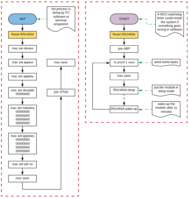
I want to show the procedure in a flow diagram that should make clear the necessary steps with RN2483A module. If something is wrong, please tell me that i can make a correction.
On the left side there is the initialization procedure where i can make it with a terminal program. Also included, but not explicid shown are the steps for initialisation (set datarate, dutycycle,channel frequency…) On the right side is the procedure made with a microcontroller.
