Don’t connect USB.
I’ve just applied 3.3 volts directly to the VIN pin, but the power consumption is still 8 mAH in deep sleep and about 20 mAH when the device is awake. I used the LowPower example. Do I maybe also need to comment out the Serial port lines in the example?
How do you measure current?
And some posts further below for current usage with LiPo connected.
I measured using a multimeter and my lab powersupply. Both show the same value. I also tried disabling the AT commands and disabling Vext via digitalWrite(Vext, HIGH) but that didn’t change anything.
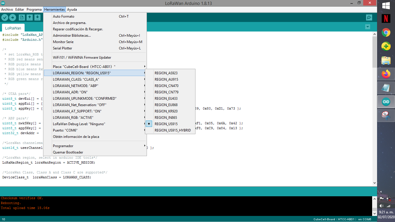
Hello, what do you mean with the sub band? and that the keys are in msb format? I don’t really know anything about it. I took the sketch of the LoRaWAN example offered by Arduino IDE, just change the code keys for the keys that TTN gave me, configure the parameters of the CubeCell HTCC AB-01 module and that’s it. The frequency band of the module and the Gateway is the same (US915). Could you please be more explicit about what I should do, review and modify?
Hello, I am not using that library. I took the LoRaWAN sample sketch offered by Arduino IDE and modified the keys (I left the keys that TTN gave me). The code only comes with these 2 included libraries:
#include “LoRaWan_APP.h”
#include “Arduino.h”
I uploaded some screenshots and the code in .txt file as support.
@bluejedi Something strange just happened. After I connected the device to the lab power supply I attached it again to usb. Immediately after plugging in I saw smoke coming from the device. I unplugged it and plugged it in again. Everything still seems to work, but the device no consumes 2 mAH more in deep sleep. Any idea what just happened?
Edit: I found out what I did wrong. I connected the lap power supply to VIN instead of VDD. I hope I did not damage the board.
OK, I checked out US915 and sub band shouldn’t be an issue.
Let’s just try and step through a few basics to rule stuff in or out.
- Make sure your antenna is connected securely
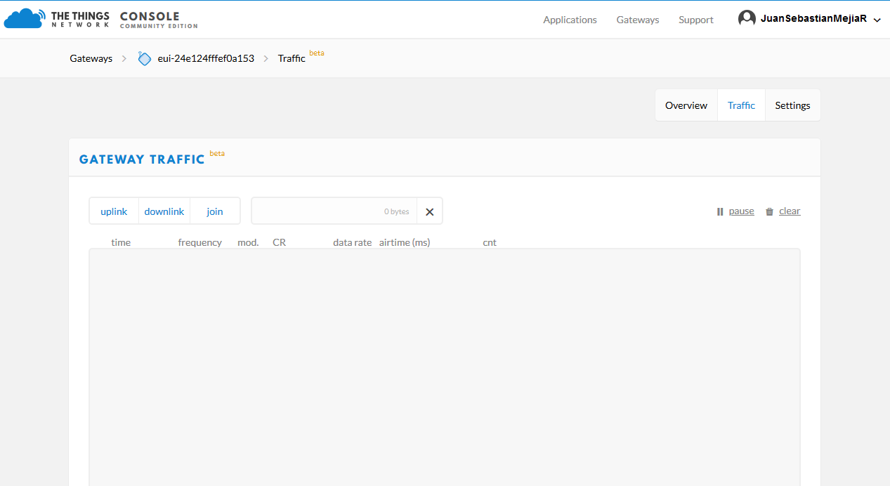
- Are you seeing traffic from the cubecell on your gateway traffic tab in the TTN console? Make sure the gateway should be in range. (edit: you already posted a shot with no traffic)
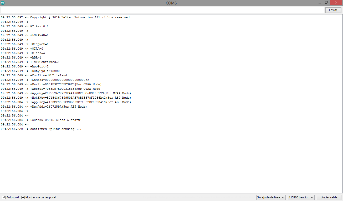
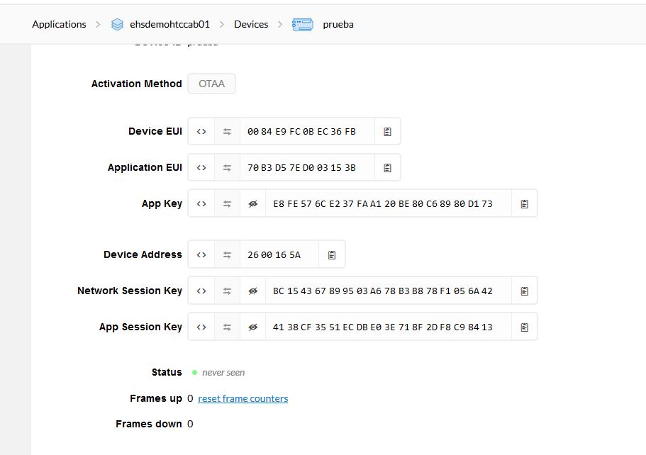
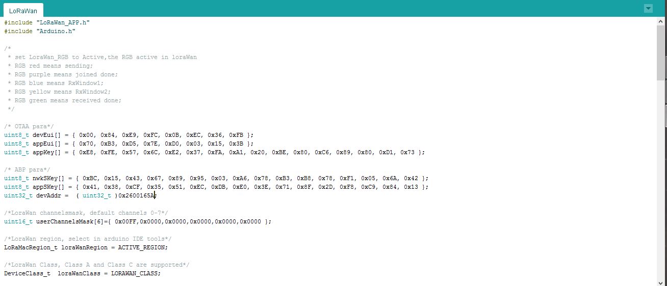
- Can you show us a screen shot of your TTN keys from the console and the keys in your code?
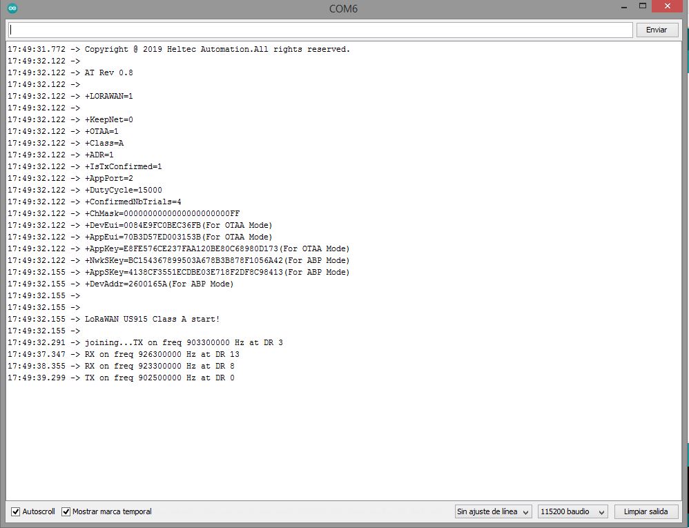
- Under the Arduino IDE tools menu - make sure you have the correct board chosen and under LoraWan debug level - choose Freq - take a screenshot of the serial monitor to show us what frequency you are using.
Try this stuff and post back some results
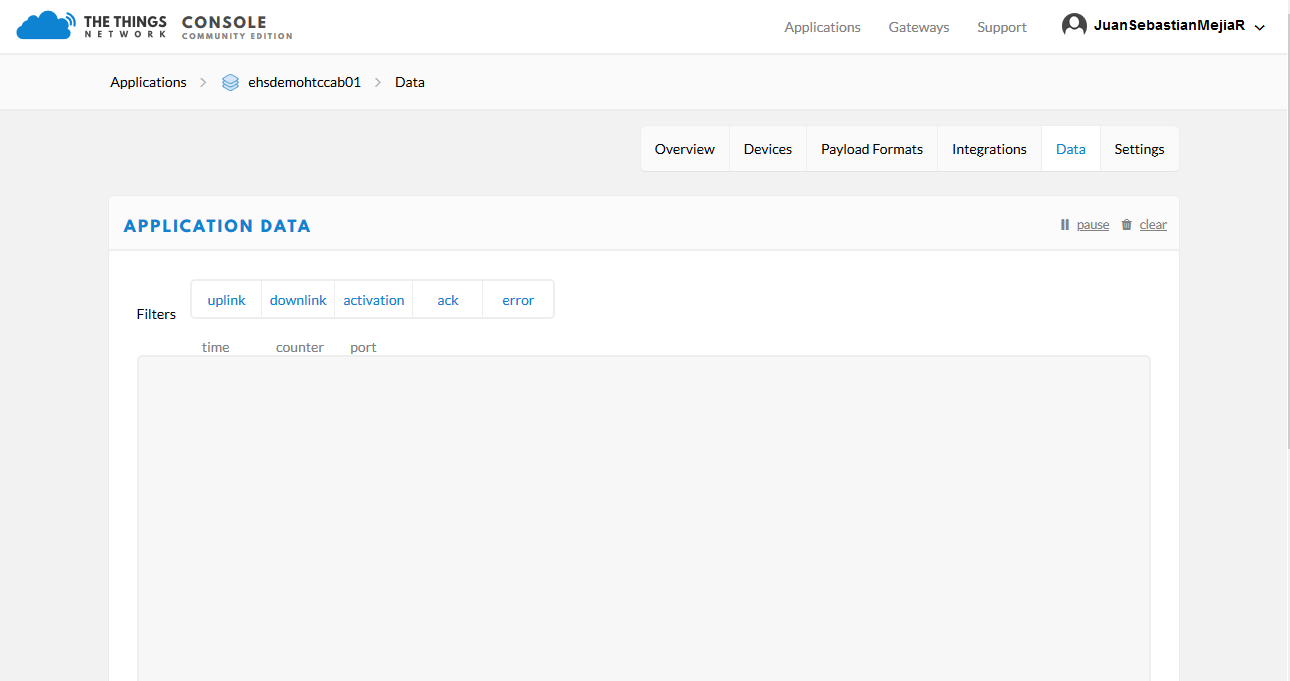
Hello, check the antennas of both the Gateway and the module and they are well connected. I still don’t see data traffic on the TTN console of the Gateway. I attach the requested screenshots. Thank you very much for your help.
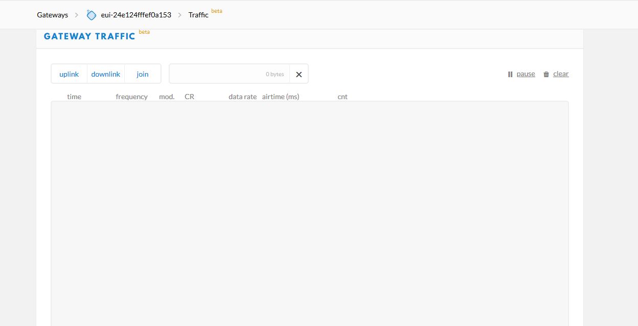
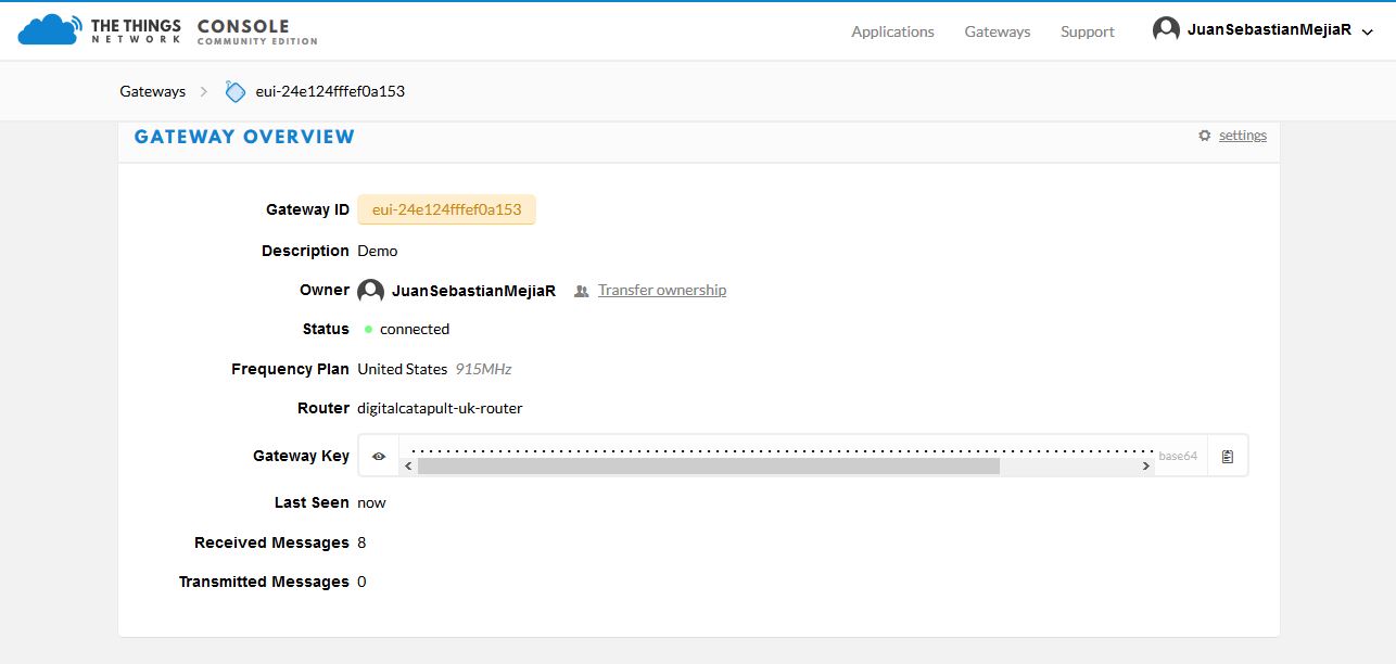
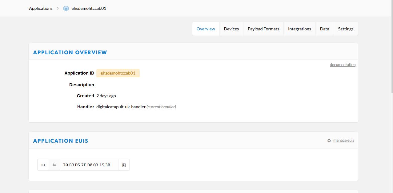
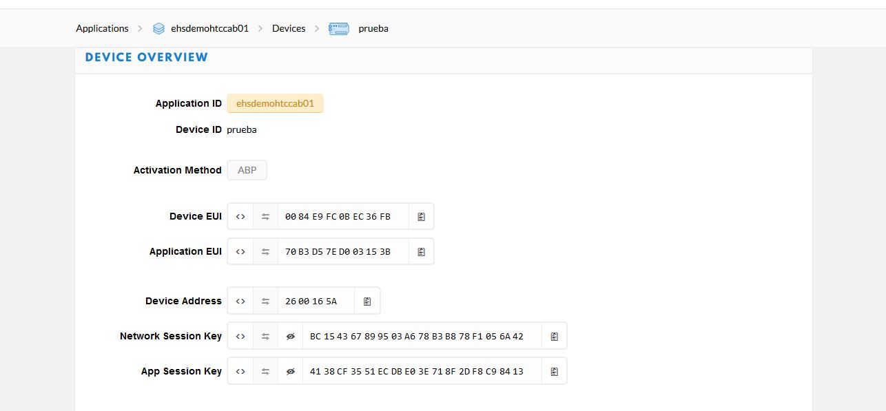
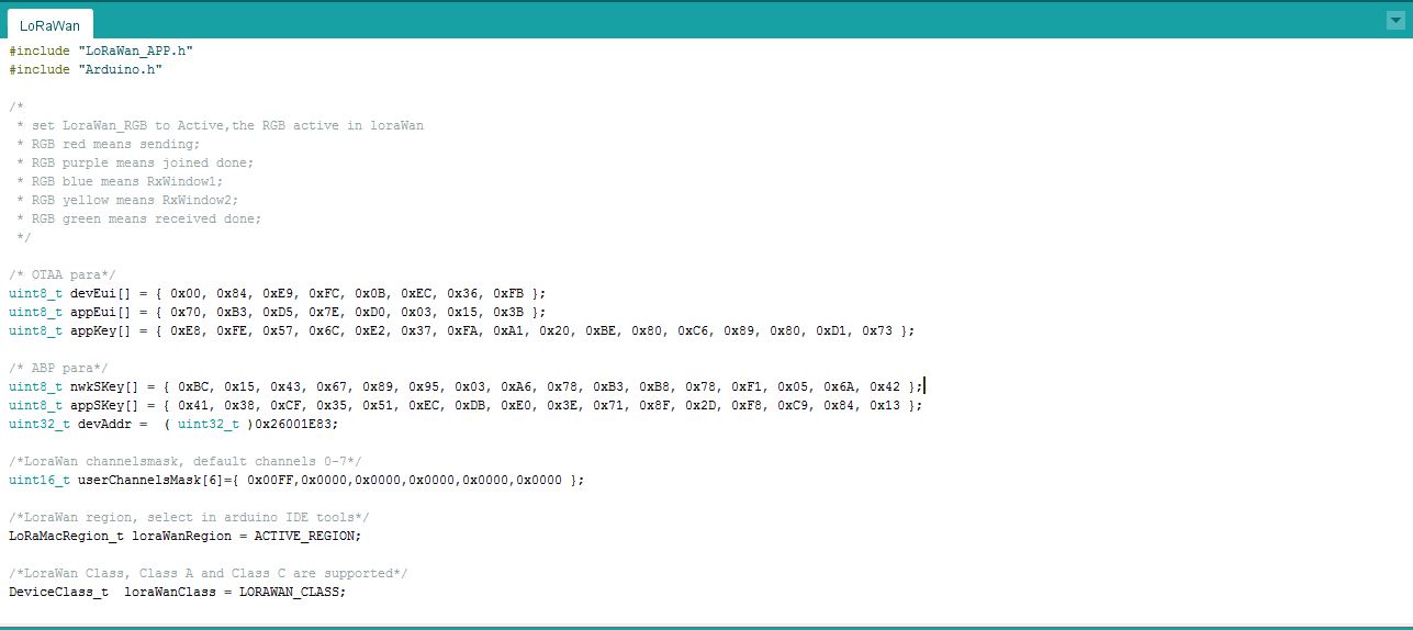
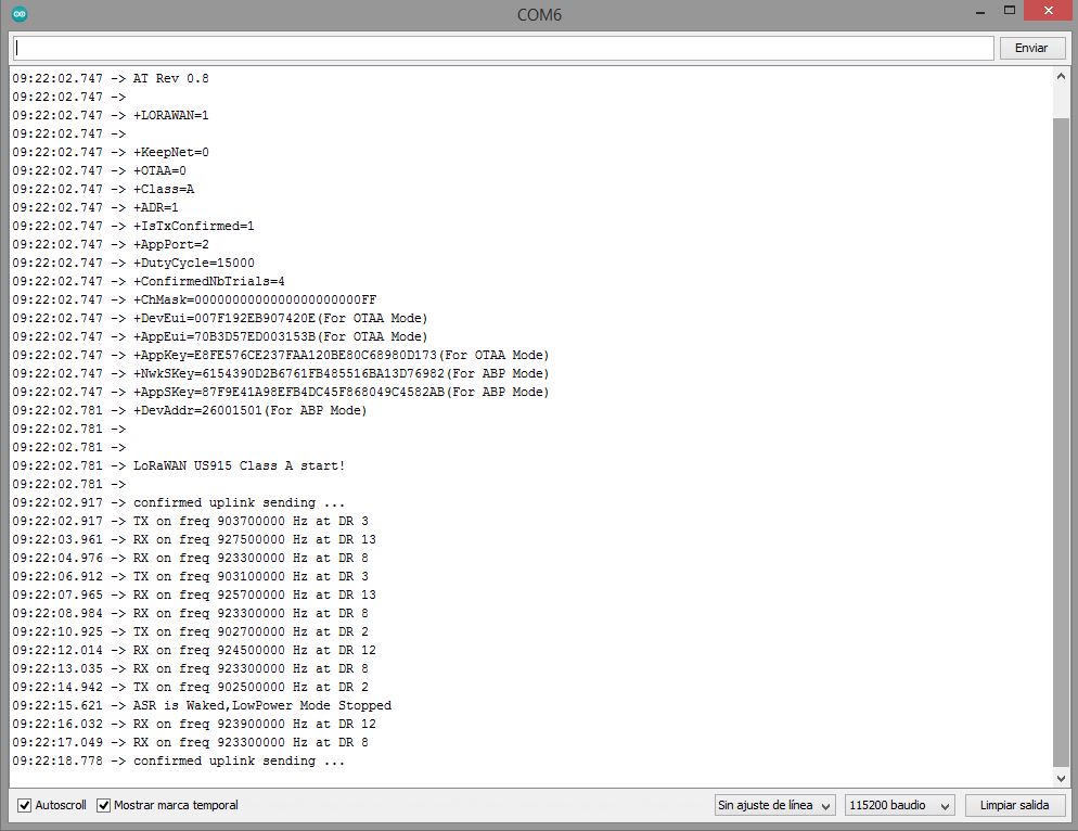
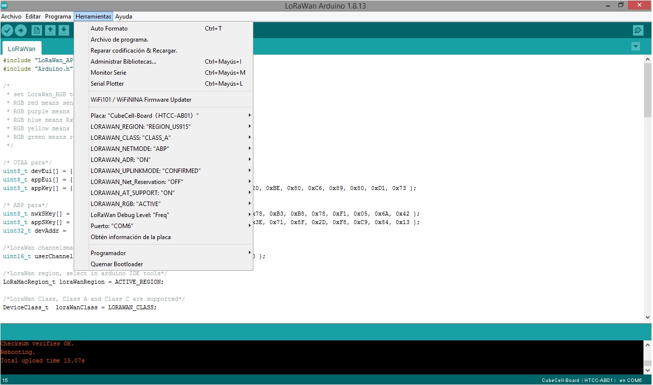
Hello, I was missing telling you that the Gateway UG87 is less than 2m away from the CubeCell HTCC AB-01 module. I also did the test with the other two CubeCell HTCC AB-01 modules that I have but still can’t get the connection, so it’s not a problem of a specific module, it must be wrong module or gateway configuration maybe.
I don’t use ABP much but I’m trying to work out why you have three different ones - sketch, serial monitor and TTN.
Have you tried OTAA? (just re-check your app key if you change back to OTAA)
Can you also show us your radio channels settings in the gateway please
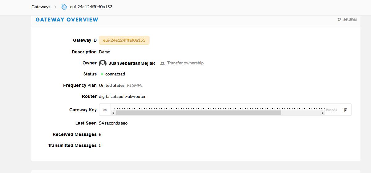
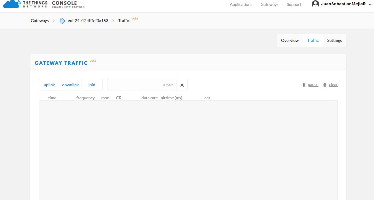
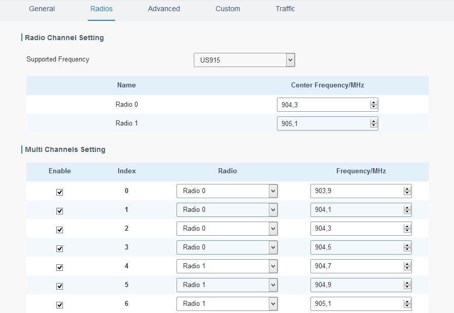
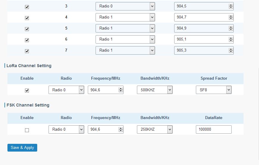 Hi, I did the test with OTAA but still can’t get it.
She means “I’m trying to work out why you have three different ones - sketch, serial monitor and TTN”.
I attach the requested screenshots. Thank you.
OK, looks like you are using sub band 1 - you can see your TX frequencies are below where your first gateway channel starts.
You need sub band 2 to be set by your channel mask in your sketch
/*LoraWan channelsmask, default channels 0-7 - 0xFF00 sets to sub band 2 */
uint16_t userChannelsMask[6]={ 0xFF00, 0x0000, 0x0000, 0x0000, 0x0000, 0x0000};Hello, thank you very much for your help. I did what you told me, I modified the channel mask (from 0x00FF to 0XFF00) and it worked perfectly. I can already see data traffic on the TTN console of the gateway and the device. Thanks to that I can move forward. Now if it’s not annoyance, I have more questions for you:
- What does the LoRaWAN sample code do exactly? How does it work? What does it perform?
- What is the difference between OTAA and ABP?
- Why if I work with OTAA connection in the TTN console of the device Frames up and Frames down are 0? When I work with ABP connection if they increase although unevenly? (Increase Frames down more than Frames up, 7 to 1).
Any information you can offer me will be of great help. Thank you again.
Has anybody run into clock/timing issues while lora is being used?
We are trying to get an ultrasonic sensor working and if we run a basic sketch to get a reading from the ultrasonic - no issues.
We have combined it with a LoRaWAN sketch, so it wakes up, takes a reading and sends.
But it seems as if the clock/timing usage of the LoRa library is messing with the ultrasonic reading timing, getting wild and inconsistent figures from the sensor.
Has anybody encountered this and overcome it?
Would it be possible to
- Wake up from sleep
- keep LoRa off
- Take a reading from the ultrasonic
- wake up Lora and send the payload reading
cheers
Paul
GPS detection with software serial is always enabled.
the Command AT+GPS=? is a get only command showing if GPS is enabled by firmware.
out testnode with a bme280 sensor is running for weeks now without problems.
