@mbirrell, you’ve replied to a 6 month old message for someone who’s in the US so the Australian network settings may not apply here …
Hi Nick, yep I realise that. I have treaversed this forum a bit and have noticed the same problem quite a few times… maybe I should have put "Make sure your Router and hadler are the same - Router (Gateway) = , Handler (Application) = " would have been clearer for the people that can’t work that out… I mean this in a good way. There are plaenty of simple things that has taken me a long time to figure out.
i already installed the library and enter the dev eui and other keys in my sketch but i can’t get any traffic in my ttn
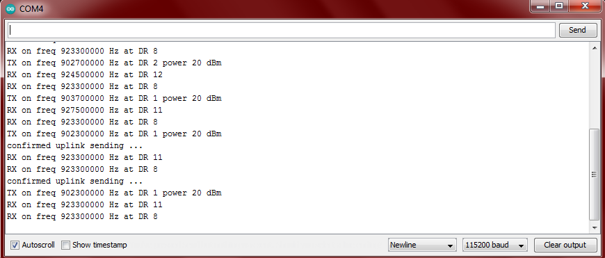
Can you show us the output from the serial port so we can see what the CubeCell is doing please.
Do you have a gateway? Or a gateway you can see the logs on? Or just a gateway at all?

Yes i have an gateway
Please can you use the Show Timestamp option so we know how often these messages appear. Please turn off confirmed uplink, it’s a burden on the gateway as it has to transmit, rendering it deaf to other uplinks at that time.
I’m not sure what all the other TX & RX activity is that is woven in to the two confirmed uplink sending lines - can you give us the url of the code base you are using.
The simplest code to start would be using ABP if you could configure for that as well.
Finally, please, no screen shots for text that can be copied & pasted, it stops us copying it in to other tools for analysis. See How do I format my forum post? [HowTo]
This is the coding i used:
#include "LoRaWan_APP.h"
#include "Arduino.h"


/* OTAA para*/
uint8_t devEui[] = { 0x00, 0x58, 0xD8, 0x09, 0xEF, 0x5D, 0x86, 0x98 };
uint8_t appEui[] = { 0x70, 0xB3, 0xD5, 0x7E, 0xD0, 0x03, 0x90, 0x67 };
uint8_t appKey[] = { 0xE2, 0xF0, 0xFC, 0xB9, 0x37, 0xEF, 0x66, 0x98, 0xD2, 0x3C, 0xD4, 0x2E, 0x30, 0x07, 0xEE, 0xF5 };
/* ABP para*/
uint8_t nwkSKey[] = { 0xEA, 0xBA, 0xB6, 0x18, 0xCB, 0x0A, 0xF2, 0xF5, 0x8C, 0x38, 0xD3, 0x98, 0x71, 0xF6, 0x16, 0xC9 };
uint8_t appSKey[] = { 0x1B, 0x83, 0x4A, 0x9B, 0x07, 0x71, 0xEF, 0x17, 0x52, 0xAD, 0x7F, 0xAE, 0x6B, 0xBB, 0xEB, 0x55 };
uint32_t devAddr =  ( uint32_t )0x26041414;
/*LoraWan channelsmask, default channels 0-7*/

uint16_t userChannelsMask[6]={ 0x00FF,0x0000,0x0000,0x0000,0x0000,0x0000 };

/*LoraWan region, select in arduino IDE tools*/
LoRaMacRegion_t loraWanRegion = ACTIVE_REGION;

/*LoraWan Class, Class A and Class C are supported*/
DeviceClass_t  loraWanClass = LORAWAN_CLASS;

/*the application data transmission duty cycle.  value in [ms].*/
uint32_t appTxDutyCycle = 15000;

/*OTAA or ABP*/
bool overTheAirActivation = LORAWAN_NETMODE;

/*ADR enable*/
bool loraWanAdr = LORAWAN_ADR;

/* set LORAWAN_Net_Reserve ON, the node could save the network info to flash, when node reset not need to join again */
bool keepNet = LORAWAN_NET_RESERVE;

/* Indicates if the node is sending confirmed or unconfirmed messages */
bool isTxConfirmed = LORAWAN_UPLINKMODE;

/* Application port */
uint8_t appPort = 2;

uint8_t confirmedNbTrials = 4;

/* Prepares the payload of the frame */
static void prepareTxFrame( uint8_t port )
{

    appDataSize = 4;
    appData[0] = 0x00;
    appData[1] = 0x01;
    appData[2] = 0x02;
    appData[3] = 0x03;
}


void setup() {
  boardInitMcu();
  Serial.begin(115200);
#if(AT_SUPPORT)
  enableAt();
#endif
  deviceState = DEVICE_STATE_INIT;
  LoRaWAN.ifskipjoin();
}

void loop()
{
  switch( deviceState )
  {
    case DEVICE_STATE_INIT:
    {
#if(AT_SUPPORT)
      getDevParam();
#endif
      printDevParam();
      LoRaWAN.init(loraWanClass,loraWanRegion);
      deviceState = DEVICE_STATE_JOIN;
      break;
    }
    case DEVICE_STATE_JOIN:
    {
      LoRaWAN.join();
      break;
    }
    case DEVICE_STATE_SEND:
    {
      prepareTxFrame( appPort );
      LoRaWAN.send();
      deviceState = DEVICE_STATE_CYCLE;
      break;
    }
    case DEVICE_STATE_CYCLE:
    {
      // Schedule next packet transmission
      txDutyCycleTime = appTxDutyCycle + randr( 0, APP_TX_DUTYCYCLE_RND );
      LoRaWAN.cycle(txDutyCycleTime);
      deviceState = DEVICE_STATE_SLEEP;
      break;
    }
    case DEVICE_STATE_SLEEP:
    {
      LoRaWAN.sleep();
      break;
    }
    default:
    {
      deviceState = DEVICE_STATE_INIT;
      break;
    }
  }
}Next time, please take a few seconds to properly format your post. Just cut-and-pasting code does not make a great message.
Im sorry about the post, Im new here and Im not used to the format writing. I thought if i post in arduino ide code format will be easier as i afraid there will be misintepretation.
By not adding formatting tags to your post the forum software will reformat it. By adding the [ code ] . . . [ /code ] (without the spaces within the brackets) tags you prevent it from messing with white space.
Ok, Mr. Kersing. Thank you
See this from my earlier message, it has all the instructions you need:
That log looks like the default code that comes with the device? are you sure you have uploaded your code correctly?
You’re in the wrong sub-band of US915.
You need to enable the 2nd bank of 8 channels, not the first.
uint16_t userChannelsMask[6]={ 0x00FF,0x0000,0x0000,0x0000,0x0000,0x0000 };
needs to become
uint16_t userChannelsMask[6]={ 0xFF00,0x0000,0x0000,0x0000,0x0000,0x0000 };
And yes, it’s confusing because bytes are being filled with words…
Thank you! I played with my Cubcell like a year ago and had no luck. Had some time to play again, and this fixed my issues instantly with their demo code.
I already changed to 8 channel gateway as previously I was using single channel gateway but still I didnt get any data traffic on ttn
There’s so little detail here I don’t know where to begin!
Which 8 channel gateway?
Does it show any information about its connection to TTN - like a log?
Does the TTN console show any information about your gateway being connected?
Do your CubeCell uplinks show up on the gateway’s log or internal console?
As previously explained, you are using the wrong channels
I already changed the sub band but still no data traffic
Show the new logs from both node and gateway