@ToomanySecrets yes, but I would not use them above 3.6V for industrial products or for customers. I like to keep voltage under maximum that are specified in the datasheet 
@N_7, yes I’m using LMIC stack.
@ToomanySecrets yes, but I would not use them above 3.6V for industrial products or for customers. I like to keep voltage under maximum that are specified in the datasheet 
@N_7, yes I’m using LMIC stack.
What kind of regulator would you use for a industrial product and what kind of runtimes do you get on your currect nodes directly under 4.2V.
It’s obvious that removing the regulator increase the battery life but if a module is rated for 3.6V max you should never consider to keep it working above this value even if it seems to work. It’s blasphemous just think it 
Any regulator that makes you get an autonomy that you can still consider acceptable. And if it does not exists, resize your claims or choose a different solution, if it exists, not to use a voltage regulator.
Alex
@ToomanySecrets
I like to keep things simple and efficient, so for me (and for Low Power), no regulator is the best option. But of course, in this case you need to use a 3V, 3.3V or 3.6V battery.
To use rechargeable batteries you’ll need a charger chip and of course a regulator, may be low drop out, and low quiescent current to keep low power.
@Charles : [quote=“Charles, post:1, topic:8059”]You can order PCB at PCBs.io [/quote]
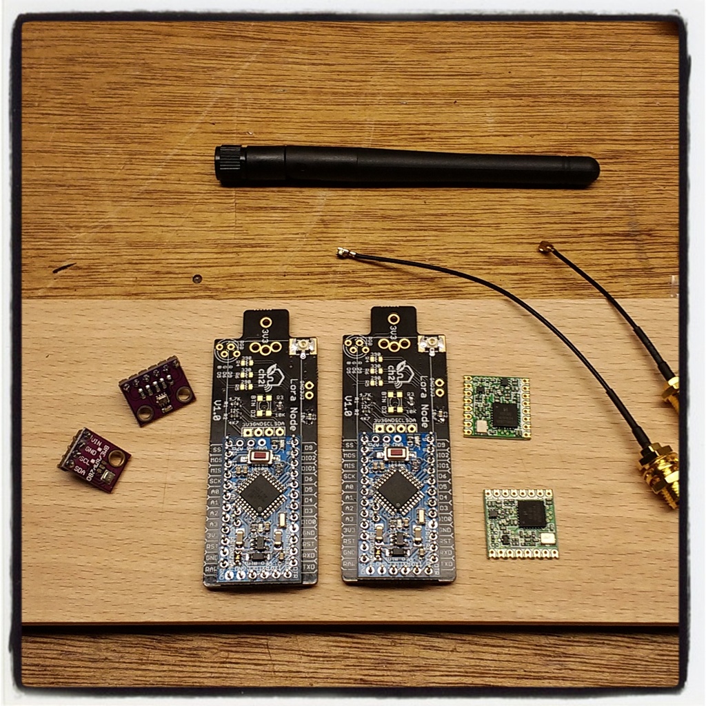
I have ordered a set of the PCB’s and they really look great and build 3 enviromental monitors with it.
Based on building those three, IMHO there can be made a few minor enhancements like :
Personal I would remove the RGB led and just add one SMD led which uses patterns (morsecode)? to indicate status (when needed) and move the button more to the side (now it can gets covered with a sensor when you mount it on the PCB) to activate
Do you have plans to release the design of this PCB on GitHub ?
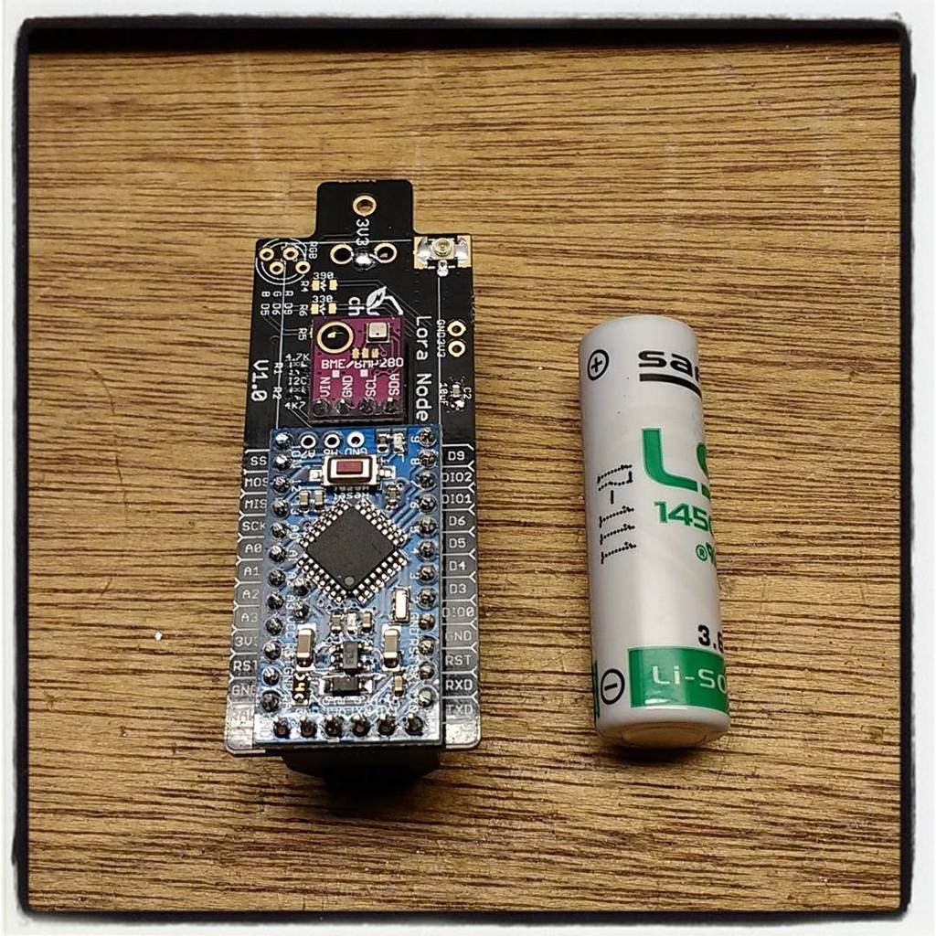
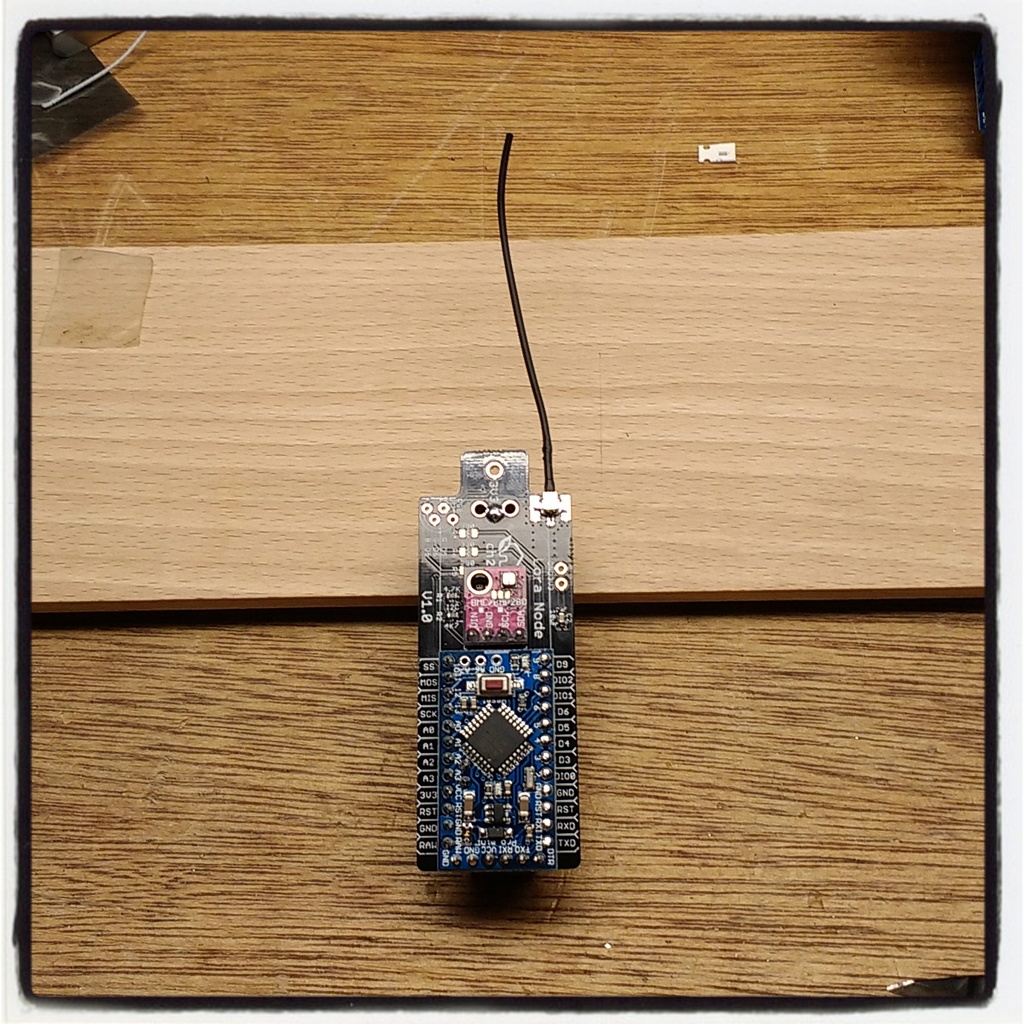
@lex_ph2lb
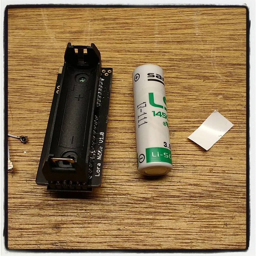
Thanks for the pictures, very nice,
Yeah for AA clip I saw that and immediately fixed it in V1.1. But I didn’t shared the board before testing. I should receive new version soon (they have been shipped). V1.1 also add SCL/SDA other pinout so you can plug other type of Arduino Mini Clones, button has also been moved 
But if you want to try before here is the link of V1.1 and even more exactly the same board with Grove connector instead
You can avoid RGB led and use the Mini on board led if you need  Avoid blink while talking with RFM since onboard led is connected to a SPI pin as far as I remember. You can also solder a 3mm classic LED and I think it’s even possible to solder 0805 RGB between 2 pins of the RGB LED.
For voltage divider (I don’t like them because of consomption and I don’t have place to control voltage measurement with controlled FET to reduce consomption).
But, I have a trick for you, you can measure VCC (voltage applied on VCC pin of ATMega) from software, that’s what I do with my ULPNode Library (you may need to adapt code) but it works like a charm, I’m doing 8 samples and Using ADC in Low Power Mode to avoid noise.
#include <avr/sleep.h>
#include <avr/wdt.h>
#include <avr/power.h>


volatile uint8_t  _adc_irq_cnt;

/* ======================================================================
Function: ADC_vect
Purpose : IRQ Handler for ADC
Input   : -
Output  : -
Comments: used for measuring 8 samples low power mode, ADC is then in
          free running mode for 8 samples
====================================================================== */
ISR(ADC_vect)
{
  // Increment ADC counter
  _adc_irq_cnt++;
}


/* ======================================================================
Function: readADCLowNoise
Purpose : Read Analog Value with reducing noise
Input   : true return the average value, false return only the sum
Output  : average value read
Comments: hard coded to read 8 samples each time
          AD MUX Channel and ADC must have been set before this call
====================================================================== */
uint16_t readADCLowNoise(boolean average)
{
  uint8_t low, high;
  uint16_t sum = 0;

  // Start 1st Conversion, but ignore it, can be hazardous
  ADCSRA |= _BV(ADSC);

  // wait for first dummy conversion
  while (bit_is_set(ADCSRA,ADSC));

  // Init our measure counter
  _adc_irq_cnt = 0;

  // We want to have a interrupt when the conversion is done
  ADCSRA |= _BV( ADIE );

  // Loop thru samples
  // 8 samples (we don't take the 1st one)
  do {
    // Enable Noise Reduction Sleep Mode
    set_sleep_mode( SLEEP_MODE_ADC );
    sleep_enable();

    // Wait until conversion is finished
    do {
      // enabled IRQ before sleeping
      sei();
      sleep_cpu();
      cli();
    }
    // Check is done with interrupts disabled to avoid a race condition
    while (bit_is_set(ADCSRA,ADSC));

    // No more sleeping
    sleep_disable();
    sei();

    // read low first
    low  = ADCL;
    high = ADCH;

    // Sum the total
    sum += ((high << 8) | low);
  }
  while (_adc_irq_cnt<8);

  // No more interrupts needed for this
  // we finished the job
  ADCSRA &= ~ _BV( ADIE );

  // Return the average divided by 8 (8 samples)
  return ( average ? sum >> 3 : sum );
}

/* ======================================================================
Function: readVcc
Purpose : Read and Calculate V powered, the Voltage on Arduino VCC pin
Input   : -
Output  : value readed
Comments: ADC Channel input is modified
====================================================================== */
uint16_t readVcc()
{
  uint16_t value;

  // Enable ADC (just in case going out of low power)
  power_adc_enable();
  ADCSRA |= _BV(ADEN)  ;

  // Read 1.1V reference against AVcc
  // REFS1 REFS0          --> 0 1, AVcc internal ref. -Selects AVcc external reference
  // MUX3 MUX2 MUX1 MUX0  --> 1110 1.1V (VBG)         -Selects channel 14, bandgap voltage, to measure
  ADMUX = (0<<REFS1) | (1<<REFS0) | (0<<ADLAR) | (1<<MUX3) | (1<<MUX2) | (1<<MUX1) | (0<<MUX0);

  // Take care, changing reference from VCC to 1.1V bandgap can take some time, this is due
  // to the fact that the capacitor on aref pin need to discharge
  // or to charge when we're just leaving power down mode
  // power down does not hurt and 15ms strong enough for ADC setup
  delay(15);

  // read value
  value = readADCLowNoise(true);

  // Vcc reference in millivolts
  _vcc =  ( 1023L * 1100L /*config.aRef*/) / value ;

  // Operating range of ATMega
  if (_vcc < 1800 ) _vcc = 1800 ;
  if (_vcc > 5500 ) _vcc = 5500 ;

  // Vcc in millivolts
  return ( _vcc );
}
Yeah will put this on github as soon as I have a descent readme to push with it 
Indeed e a resistor divider will drain the battery but you’re ADC idea look good.
I will try it you’re code snip (and order a aditional set of PCB’s). 
BTW, any reference for your UFL Antenna ? looks nice 
Working on that. Need to do some measurements to get it right but for now it’s close to where I want it.
When I find the optimum I will post it here.
how did you squeeze the code?
mine needs: Sketch uses 30676 bytes (99%) of program storage space. Maximum is 30720 bytes. only as LoRa node.
my BME280 routine (could be shrinked by some text) needs: Sketch uses 11244 byte.
so that does not fit into the proMini
used libs for LoRa: lmic.h , hal/hal.h , SPI.h
used libs for BME: Adafruit_Sensor.h , Adafruit_BME280.h
probably you could share your code?
thanks
@ursm
First of all I change the default bootloader to optiboot one, this save me 1.5K of code allowing sketch of 32256 size. I also programmed it with 250K upload which is much faster and reliable at 8MHz. See my post about this
Then I avoid importing any library, I just grab the minimal code from Lib that I integrate into my own lib after optimisation.
Also remove some debug print, and set LMIC to no debug with
#define LMIC_DEBUG_LEVEL 0
as example with SI7021 + TSL2561 sensors (both in the same sketch sending to TTN) with no debug I’ve got
Sketch uses 26376 bytes (81%) of program storage space. Maximum is 32256 bytes.
Global variables use 1297 bytes (63%) of dynamic memory, leaving 751 bytes for local variables. Maximum is 2048 bytes.
Same with my debug activated
Sketch uses 30450 bytes (94%) of program storage space. Maximum is 32256 bytes.
Global variables use 1303 bytes (63%) of dynamic memory, leaving 745 bytes for local variables. Maximum is 2048 bytes.
Amazing with CCS811 and my debug activated with also SI7021 and TSL2561
Sketch uses 30976 bytes (96%) of program storage space. Maximum is 32256 bytes.
Global variables use 1303 bytes (63%) of dynamic memory, leaving 745 bytes for local variables. Maximum is 2048 bytes.
I’m sorry, for now the code is not open source, it’s a compilation of 2 years (not full time) of research and optimisation and used for private customers. I intend to add BME280 on my lib, I’m pretty sure I can add it with some opt. I think I’ll use this one https://github.com/finitespace/BME280 as starting point.
I think I’ll be able to share the I2C stuff of the library. Let me think about that.
mine needs: Sketch uses 30676 bytes (99%) of program storage space. Maximum is 30720 bytes. only as LoRa node.
Thats too much, i would guess you use the wrong version of the lmic here. Delete the one you use and go grab the one from here: GitHub - matthijskooijman/arduino-lmic: ⚠ This library is deprecated, see the README for alternatives.
lmic.h, hal.h, SPI.h and LowPower.h + working code for OTAA (without the tricks from Charles) is 20358 Bytes for me. If i would use special bootloader, optimize the lmic (debug level), i could go even lower.
You allready got great advice from @Casper and @Charles.
My 2 cents to this topic : as @Caspar sugested using the Mathijs version of LMIC is a good start. Next, remove all the debug stuff you find in the examples. And what you want to debug, just use simple output (for example : “S” for start. “T” for transmit, “ET” for event timeout etc).
For example in the LMIC example you see code like this :
Seriel.PrintLn(“EV_TXCOMPLETE (includes waiting for RX windows)”);
Why not change it to :
Seriel.PrintLn(“ETXC”);
That saves quite a few bytes of code. Or even better if you’re interested in the OnEvent event just print it and dont make it human readable with debug output in every case from the switch.
Also check you’re libraries, remove anything that isn’t needed or write you’re own dedicated libraries by stripping down a standard library like @Charles pointed out For example when you only use the I2C to communicate with the BME280, why have a library with a large chuck of SPI code in it. .
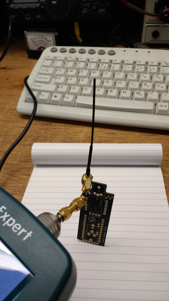
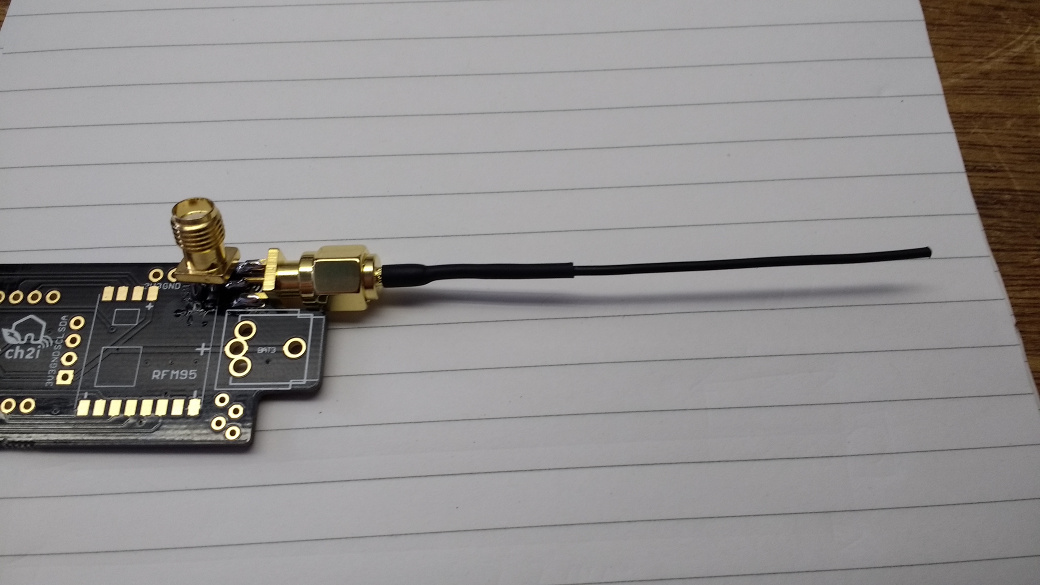
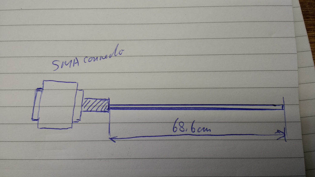
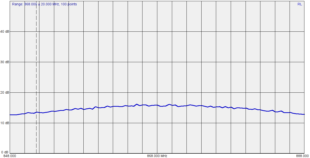
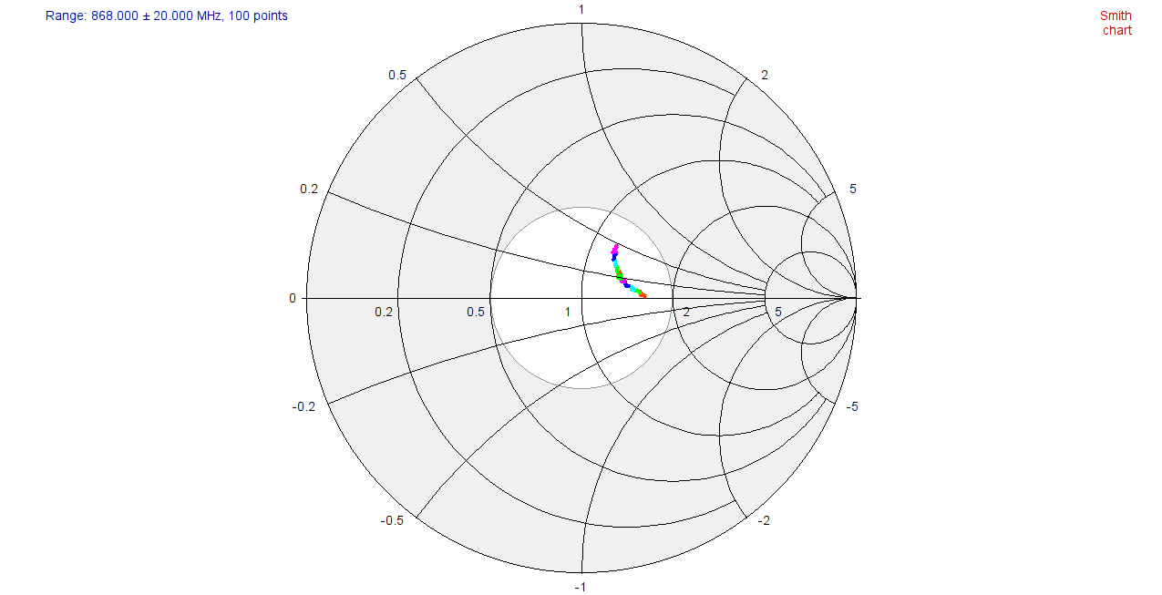
@Charles : Today I rebuild the antenna and made some measurements on it while constructing so the influance of the PCB is used in the building process.
I left 2 cm of the coax shield on the connector side and used heatschrink to make it more stiff.
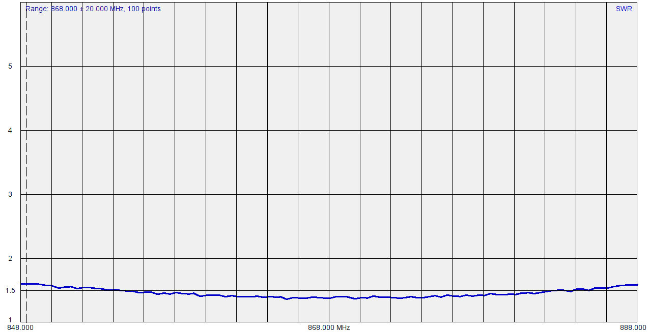
Below you find the graphs SWR, Returnloss and smit chart.
The return-loss is very acceptable.
Took a minute to wrap up this code in a example and it works out of the box. Many thanks for sharing. ![]()
Yeah forgot this one, in default example I changed debug output to use flash memory.
Serial.PrintLn("EV_TXCOMPLETE (includes waiting for RX windows)");
this is not using Flash space but RAM (if not let me know, something changed) so it won’t optimize flash in any way, you need to use F() macro as follow to place string in flash. But @lex_ph2lb advice if correct, to reduce size, reduce print strings lenght (as far as they stored in flash)
Serial.PrintLn( F("EV_TXCOMPLETE (includes waiting for RX windows)") );
@lex_ph2lb thanks for antenna reference, nice graph and interesting
Oeps indeed, forgot to mention the F() macro. ![]()
[quote=“Charles, post:42, topic:8059”]
@lex_ph2lb thanks for antenna reference, nice graph and interesting
[/quote] You’re welcome. This week I want to setup some field trails to test it against a stock antenna. But for now it looks really good.
Guys
Just to let you know I’ve integrated for testing some tweaked BME280 code in my library. I need to take time to test but, as reference, it fit with TSL2561 code sensor even on Mini without Optiboot Bootloader
With no debug leaving space

With some debug activated, as you can see, still fit 

Remove the bootloader entirely and get a cheap ISP AVR programmer from eBay, you’ll be able to use the full 32KB of progmem.
Time for a new antenne experiment. Now with the SMA chassis part and a single wire mounted in the SMA connector pin.
