This PIN 10 is use for sx1262 module but as per sx1302 datasheet they have mention 1.1 RF Front End Interface The SX1302 is intended to be used with various RF Front End chips (RF to IQ), such as Semtech’s SX1255/57. Details on the
**interface and compatibility is available on Section 4. “RF Front End Interface” ** " The SX1302 can accommodate any of the following RF front-end devices: SX1250, SX1255 and SX1257" all of which are Semtech products. For any other device, hardware logic could be used on the interface for translation purposes. The roles of these devices is to down-convert the RF signal to baseband (direct conversion or low-IF), and digitize it to feed the IQ samples to the SX1302 baseband chip. The interconnection to the front-end device is organized as follows. Here, the SX1250 is taken as an
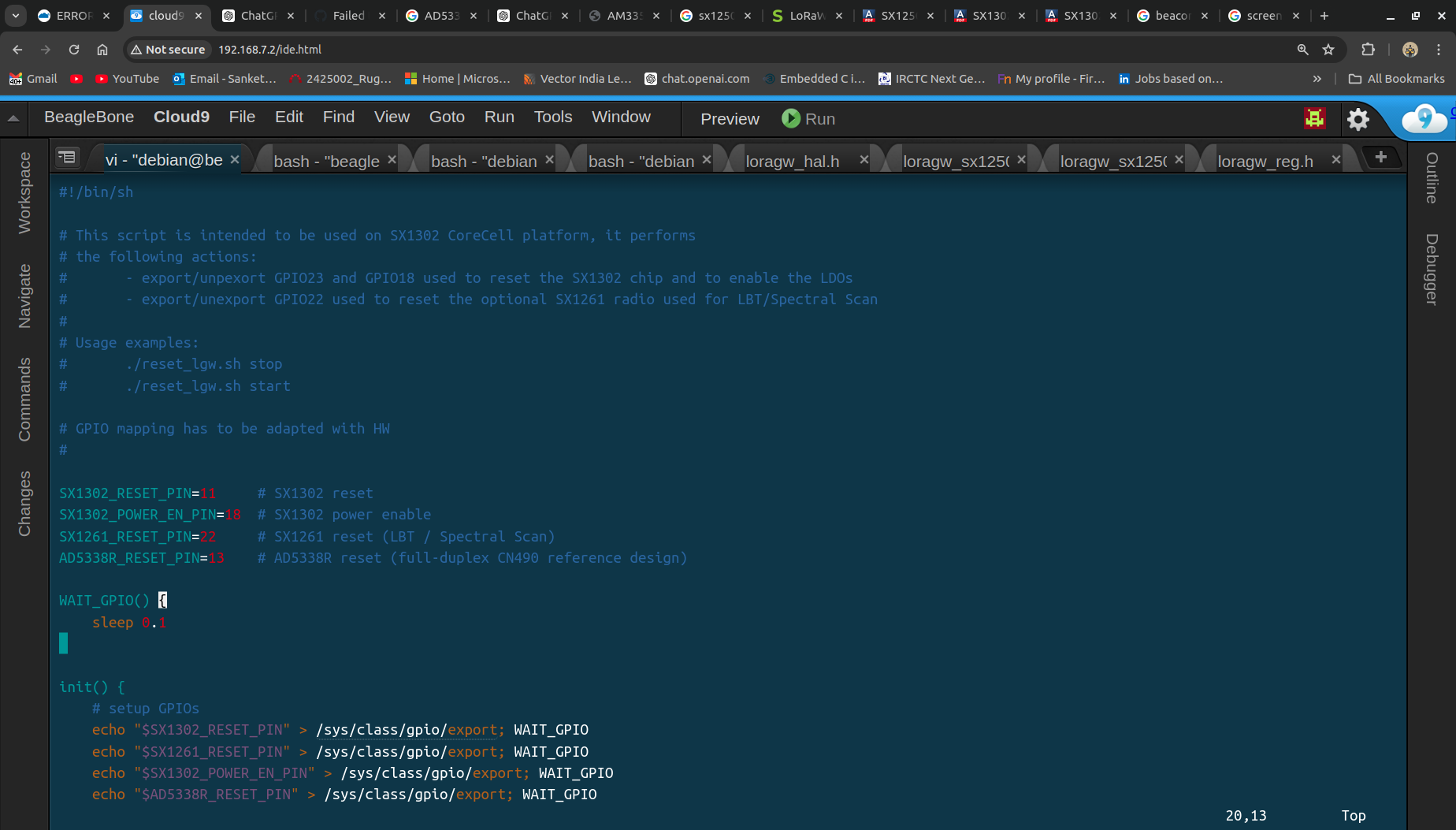
and one more thing as per sx1302_hal_lib library mention the this pin optional “# - export/unexport GPIO used to reset the optional SX1261 radio used for LBT/Spectral Scan”
I think this pin is not useful but I don’t no… i’m right or wrong so please let me know.
In screenshot four configuration pin first reset pin i have configure but reaming 3 pin .I can’t understand what is use of this pins ? where is connected ?
You don’t have to quote datasheets for me. If you do, please use the formatting tools found at the top of the input textbook to properly format the text.
Do you have access to an oscilloscope? I am wondering if there is any activity on the SPI pins at all. Ditto for the sx130x reset.
Please use the toolbar correctly - code & log snippets should be formatted with </> - and it doesn’t need describing before hand because you pressed the button early - select the text, then the tool - it’s indicative of rushing …
That you aren’t answering the questions asked when someone is trying to help debug your issue? If you want help we expect you to help us help you. We don’t have your hardware or your issue, don’t expect us to have crystal balls that suddenly provide the solution to your issues.
Very few people use beaglebones for the LoRaWAN gateway so there is not a lot of experience in this regard. I happen to have a commercial offering based on a beaglebone green that I thinkered with so that’s why I’m trying to help, however there is a limit on the amount of time and effort I am willing to spend helping people with non standard setups, it’s my spare time you are consuming.
Thank you for your guidance regarding the issue but i’m new in this field so i need guidance. you are asking about the oscilloscope ya i was checked on DSO and signal are showing when was run the code . hardware connection :
lorawan beaglebone
SX1302_CSN(pin_51) …> P9-17(SPIO_CSO)
SPI_MOSI(pin_49) …> P9-21(SPI_DO)
SPI_MISO(pin_47) …> P9-18(SPIO_D1)
SPI_CLK(pin_45) …> P9-22(SPI_SCLK)
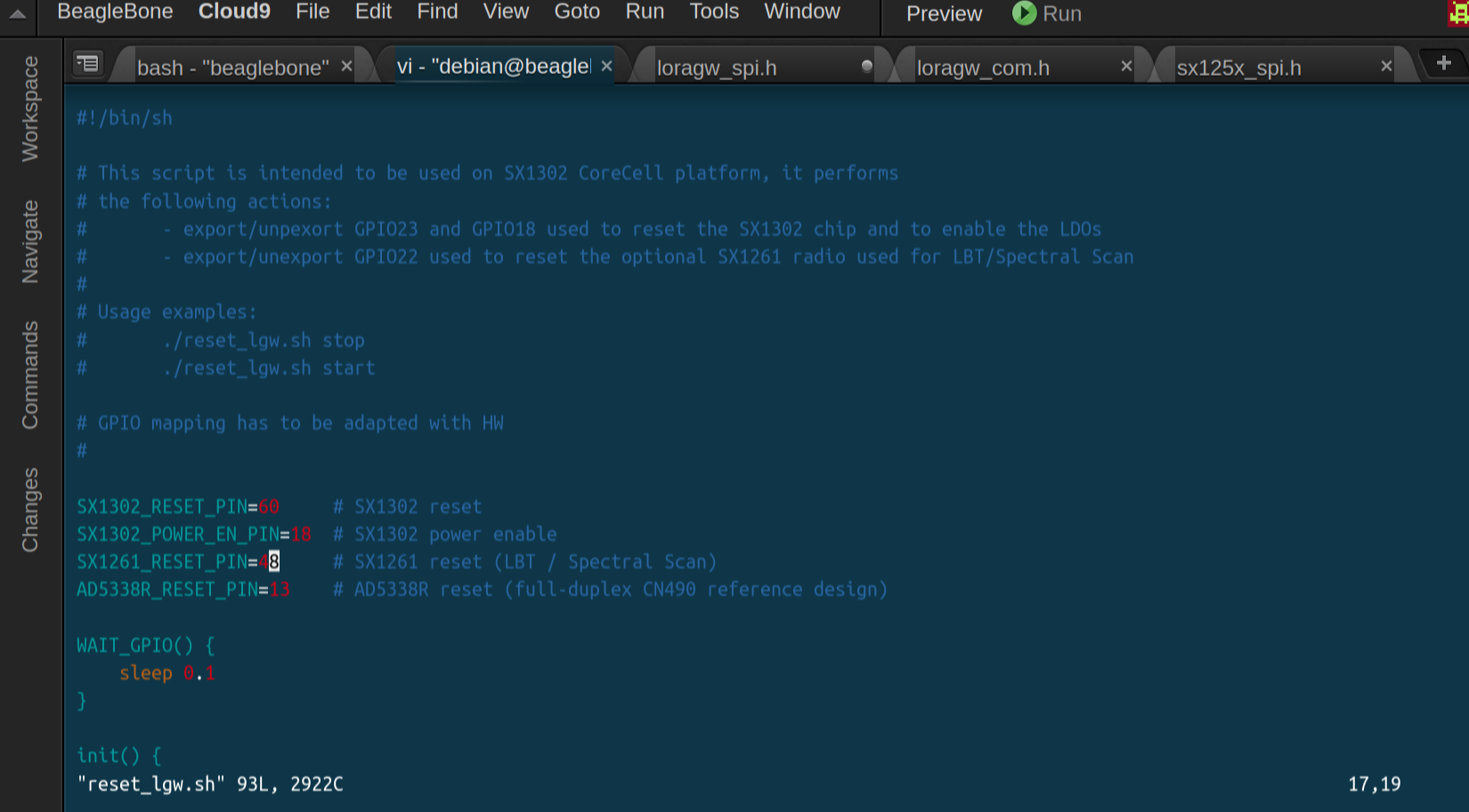
SX1302 RESET(pin-22) …> P9-12(GPIO_60)
SX1262 RESET(pin-10) …> P9-15(GPIO_48) ( additional )
i will show you the config file
when i was debugging the code. I’ve understand the one more thing read function is read the dummy data(0x00)or (0xFF)
Note: chip version is 0xFF (v15.15)
freq_hz=867500000
buff[0]=0xff,buff[1]= 0xff buff[2]=0xff (printf function use what they read into the buff array)
what is behind the reason ? I still facing the Image calibration issue. I was tried everything in my side.
I’ve need just one breakthrough .what i’m missing ?
Which beaglebone model are you using? How did you enable SPI? Have you checked the SPI chip select is actually activated? How do you connect the beaglebone to the Lora module?
In that case you make your life a lot harder by using non standard hardware.
When showing configuration settings that are plain text please copy and paste, don’t use graphics for text, text is easier to read and gets indexed by the search engines.
Can you wire up a known good SPI device like an accelerometer or ADC or similar to check SPI is working as you expect.
Quoting data sheets or code to people that don’t own a BeagleBone won’t move things forward as we aren’t familiar with it. You need to try something other than repeating the same thing over & over.