Big ESP32 + SX127x topic part 3

Hi,
First thanks for your answer.
Then here are the details informations :

  • I use a Heltec module : OLED WIFI Lora 32.
  • I work with Arduino IDE 1.8.13.
  • as working board, I select "Tools, Heltec ESP32 Arduino, WifiLora32(V2)
  • I use the MCCI LoRaWAN LMIC library, downloaded from github
  • its version is 3.2.0.
  • I open the sample file “ttn-abp.ino” from example directory.
  • the compilation doesn’t give an error message.
    After your last message do I clean my libraries and download the MCCI LoRaWAN library.
    Thanks for the recommandations of your last message.

Before going in the modification of this sample program, can you confirm that I’m working on the correct sample program for my module.

Thanks before hands,

They aren’t specific to a module but that is the best one to start with - you will need to set up the pins - the I/O for the module - so you’ll need to look at the documentation for the Heltec module and read down through the code to the pins section.

You should read the Topic Start carefully.

OLED WIFI LoRa 32 is not the correct full name of your board.

Your board is one of the following:

  • Heltec Wifi LoRa 32
  • Heltec Wifi LoRa 32 V2

V2 will have “V2” marked on the PCB.

The available Heltec Wifi LoRa 32 boards are listed exactly as follows:

  • Heltec Wifi LoRa 32
  • Heltec Wifi LoRa 32(V2)

The board you select must match your hardware. Select V2 only if you have a real V2 board.

As described in the Topic Start ttn-abp.ino is the correct example sketch to start with.
Important is to use the correct pin mappings and corresponding software configuration settings for your board. These are also described in the topic start.

Also note the I2C (SCL, SDA) remarks for V2 in the Topic Start. These are essential for getting the OLED display or other I2C peripherals to work (after you have the basics working).

For the correct format of the LoRaWAN keys and ID’s see:
Format of Keys and ID’s for Arduino LMIC libraries [HowTo]

Thanks bluejedi for this answer.
My module is really a V2. So the correct description is Heltex Wifi Lora 32 (V2).
I use this definition in the selection of my hardware.
Now I will check the pin mappings carrefuly. This part is not so easy and I appologise for those kind of question.
I will give you feedback as soon as possible.

Have not been active with my nodes for a while (they worked) but have started tinkering with the wireless stick lite and cubecell AB01. Both have impressive standby currents in my view of well under 1 ma while powered on battery (nothing connected to the usb interface).

With both using only a provided lipo I was seeing currents down to 40-50 uA. While the cubecell has a different architecture I was especially impressed with the wireless stick lite given that it has the full ESP32 onboard; had not seen such standby currents yet, especially not given that it has integrated lora peripherals as well!

Please note that I was trying to get down to the lowest power consumption and hence was using a clock speed of 80mhz for the wireless stick lite vs the standard 240mhz. All lora transmissions worked properly using the MCCI library OTA example (nss: 18, rst 14, dio { 26,35,34).

Also looking at the cost (around 12 euro excluding shipping) these are real gamechangers in my view!

1 Like

Was that for the Wireless Stick or the CubeCell?
The CubeCell HTCC-AB01 should be able to get (much) lower than 40 uA.

If you don’t need WiFi and Bluetooth you should be able to clock the ESP32 even lower, down to 10 MHz. See: ESP32 power consumption at different CPU speeds

Hello! I am trying to use ttgo t-beam v1.1 but the only way I could find was using paxcounter project. I would like to write my code as I wish and be able to deep sleep the device, put a button interrupt, connect to TTN and send the data in the format I choose. The paxcounter project let me connect to TTN, but I can’t do what I want because I am not so good at modifying that code (which is very ample). Is there any alternative for this simplist app I’m trying to create? Thanks.

T-Beam versions 1.x have a special power management chip.
For T-Beam specific things I suggest to visit the TTGO T-Beam topic instead.

Paxcounter is rather complex if you only want to write some basic code yourself.
For connecting to TTN you might want to start with the basic examples from the MCCI LMIC library as described in the topic start.
Note that you will have to use the proper pin mappings for your T-Beam version and that you have to enable/configure the power management chip (see T-Beam topic).

First try to get these basics working, from there you can extend the code with support for GPS and other things.

Keep in mind you only connect to TTN once and need to store the ‘connection’ information. You can not join every time you want to send data because you will run out of join opportunities.

I appreciate very much your answers! Thanks for the fast replays! Before trying the Paxcounter (the only way I succeded to connect to TTN) I tried LMIC library but with no succes. Now after you suggested me, I started on git an issue because I can’t succed in running the ttn-otaa.ino example from LMIC. Have a look here please! Thanks.

In this topic you have not provided any information whatsoever so I’m not sure what you expect from filing an issue for MCCI LMIC on Github.

Your issue will very probably not be caused by a shortcoming in MCCI LMIC.

If you want to get any useful input on this forum you will at least have to provide sufficient detailed information about your problem, what exactly is not working, what you have tried, what sketch you are using, what settings and pin mappings you have used, what error messages do you get, etc.

You can use the search option to find any relevant information for your issue on the forum.

Also don’t paste links without any further description (e.g. Github).
Users on the forum don’t like having to go elsewhere to read your information.

Try the steps already described on the forum.
If something is not working it is usually ones own fault (e.g. incorrect settings used, typo’s, not carefully following steps provided) and not because a bug in examples, libraries etc.

And if you do not setup the power management chip on a T-Beam v1.x correctly then it will not connect to TTN.

I just started my first baby steps with LoRaWan after buying two Heltec WiFi LoRa 32 V2. Living in an urban city the nearest GateWay is out of range and most likely is the standard antenna not helpful. Closer to this gateway I think I was able to connect or at least get a reaction from this gateway. My first working (?) sketch was made with the OTAA.ino sketch from https://robotzero.one/heltec-lora32-lorawan-node/ and solely changing my Heltec/TTN credentials. Found some references in this forum like here likely I should migrate to MCCI LMIC but this was the easiest first attempt;).

Some questions (likely missed reading them in the forum):

  • what kind of range can I expect with this Heltec, will a different antenna be an improvement?
  • can I continue with this sketch or is diving in MCCI LMIC a better option?

How far ‘out of range’?
If a different (better) antenna will make any difference depends on different factors, like distance, antenna placement, obstacles etc.

You may possibly need to setup your own indoor or outdoor gateway.

Improvements are possible but depend on different factors, one being the antenna’s included with your Heltec boards. You have not given any details about your antennas. The type of antenna’s included will depend on region and probably on time of production, time and location of purchase and availability.

Also have a look at:

If you want to do and learn anything more than just running someone else’s sketch then reading documentation and learning the essentials will be useful.

This topic (start at the top) and other topics on the forum contain useful information to help getting you started.

1 Like

@bluejedi thanks for your response.

  • I live 1,3 km from this gateway, a field trip into the cold gave a positive reading at 400 meters (positive as in joining - joined - sending). This was done with the standard antenna sold with the product. I am not able to check the quality of this antenna and to determine this is a fair result with on the other side an indoor gateway.
  • Personally I prefer a good working sketch as starting point to make your own variations but also agree with a more or less RTFM approach (thanks for the antenna topic); think the answer is yes on my question “is MCCI LMIC a better option?”

Maybe, maybe not. The LoRaWAN source used by Heltec is from the original Semtech code base, the people that invented LoRa.

The MCCI LMIC is the continuation of code that has passed through many hands over the years and has proved it’s worth for smaller MCU’s but still has it’s foibles.

Depending on what you are trying to achieve depends on where you go next. If you want to experiment with devices at the LoRaWAN level, then dig in to both code bases. If you want to deploy devices with some useful sensors on, which requires a fair bit of firmware development & testing and get stuck in to the data presentation & analysis, then I’d stick with what’s working. You can of course do both if you have a lot of time on your hand or a really big brain, preferably both.

1 Like

That is a fair result. For a gateway with the antenna indoors distances differ from <100m to a few kilometers but mostly 100-600 meters in my experience. (A lot depends on the materials used in the building)

1 Like

Friends:
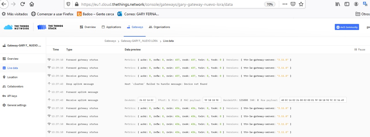
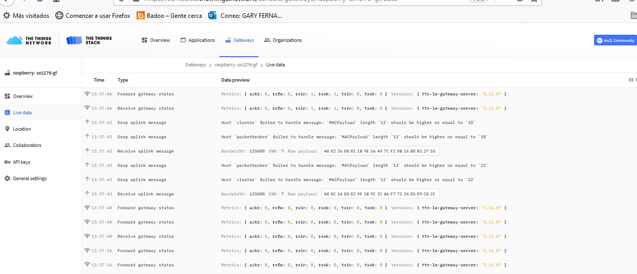
I am using a TTGO v1 with a DTH11 sensor to send temperature and humidity, I use the MCCI_LoRaWAN_LMIC library
with version 1.5.1, using the example ttn-abp-feather-us915-dht22.
I use the V3 of TTN for the new changes for 2021.
I have 2 gateways (one channel) and both the sending node and the receiving node (903.9 MHz) channel 0 are configured on the same frequency.
However, I get these errors and the data is not uploaded to the platform.
Could someone help me, maybe something needs to be changed in the library or in the TTGO programming? GATEWAY-NUEVO1 GATEWAY-RPI

I’m sorry for you but we do not support single channel packet forwarders on the forum.

See: Single Channel Packet Forwarders (SCPF) are obsolete and not supported

1 Like

thanks.

<rant-mode>

Some examples of inconsistencies in LilyGO/TTGO documentation.

In this case for TTGO LoRa32 V1.3 (aka LoRa V1.3, aka T3 V1.3).

Part of the circuit diagram:

Notice that the LoRa32 V1.3 circuit diagram is actually placed in the T-Beam repository which is a totally different product. The information is not where one expects and will try to look for it.
LilyGo also have a website which unfortunately hardly provides (better detailed) information about their (LoRa) products and is again made difficult to find.
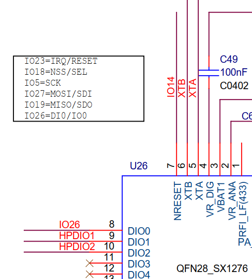
TTGO T3 V1.3 partial circuit diagram

What the above says:
SX1276 Reset is connected to ESP32 GPIO14 (diagram)
SX1276 Reset is connected to ESP32 GPIO23 (textbox)
Only one of these is correct. Now you figure out which one…

The information in the textbox shows “IO23 = IRQ/RESET” but IRQ and Reset are not the same and do not use the same pin!
What is often incorrectly called IRQ on these boards is actually the DIO0 pin from the LoRa chip which on TTGO LoRaWAN boards is connected to the ESP32’s GPIO26 pin and not GPIO23.
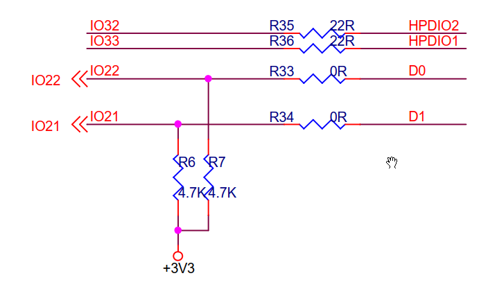

TTGO T3 V1.3 partial circuit diagram (2)

According to the circuit diagram:
Display D1 is I2C SDA = ESP32 GPIO21
Display D0 is I2C SCL = ESP32 GPIO22

However, in practice this appears not to be true,and instead:
SDA = GPIO4
SCL = GPIO15


The same repository contains a product link for the TTGO LoRa32 V1.3 that points to the LilyGo shop on AliExpress (in Portugese!).
The page contains a pinout diagram for the TTGO LoRa32 V1.3 (aka T3) that contains the same incorrect?? I2C pins information:

TTGO T3 V1.3 I2C pins (1)

A month ago I copied the same pinout diagram and then it showed:

TTGO T3 V1.3 I2C pins (2)

As said before, in posts from others SDA in pratice appears to be GPIO4 and SCL appears to be GPIO15. Which is as shown on the pinout diagram from a month ago, while the pinout currently shown on their shop’s product page shows SDA = GPIO21 and SCL = GPIO22.
I don’t have the board so I am unable to verify it.

The different pinout diagrams do not show a document version or document date.


What to believe here? Who / what is correct and when?

Without actually having the boards to verify it is impossible to know which information is correct.

Will we soon see a batch of new boards with same version number where the IC2 pins have suddenly changed?


Deficient documentation and contradicting information like above make it hard to keep information in this topic up to date and reliable (and this hasn’t improved much over time).

It also does not give much confidence in these products. If essential information and documentation keep having/getting errors and inconsistencies then why would one expect the products themselves and their design to be any better?

</rant-mode>