Big ESP32 + SX127x topic part 3

Recent TTGO product T-Watch belongs to a ‘wearable appliance’ category. And like majority of their products, the T-watch is also based on ESP32 SoC.
This is an option to buy the watch together with ‘GNSS+LoRa daughterboard’ which has SX1276 RF IC (been wrapped inside S76G SoC) and LoRaWAN compliant firmware built-in.
The RF daughterboard performs quite well, provided that external SMA antenna is in use.

Below is an illustration of how SoftRF firmware is driving the watch to transmit and receive packets with LoRa modulation (FANET protocol):

3D design of ‘cargo bay’ for the T-Watch is available on my Thingiverse page.
It is designed to fit for two SMA <=> uFL/IPEX adapters.

Is there a software for the S76G, which replicates the SX1276 signals on GPIO pins? This way LMIC stack could be run on the watch.

I have a TTGO LORA32 board that I am going to use as a soil moisture sensor, however the results of esp_deep_sleep_start() is underwhelming. I have the consumption down to ~15mA when sleeping, but I was hoping/expecting to get down to double-digit uA.

I’ve noticed that the moisture sensor continues to draw current when the ESP32 is in sleep (~5mA), so it looks like there is more to be done with the config.

My current setup is:

esp_sleep_pd_config(ESP_PD_DOMAIN_RTC_SLOW_MEM, ESP_PD_OPTION_OFF);
esp_sleep_pd_config(ESP_PD_DOMAIN_RTC_FAST_MEM, ESP_PD_OPTION_OFF);
esp_sleep_pd_config(ESP_PD_DOMAIN_RTC_PERIPH, ESP_PD_OPTION_OFF);

and rtc_gpio_isolate doesn’t compile.

Does anyone have a working config or suggestions on how I can better reduce deep sleep power consumption?

TIA.

Long discussion about similar problems on the ESP32 support forums;

A bare bones ESP32 board, with a carefully selected regulator, may well get down to 30uA or so in deep sleep, but very often the boards are not designed for that.

Most ESP32 boards have components that may consume current even when the ESP32 device itself is in deep sleep; USB-Serial devices, displays, charger ICs.

I’ll have a read.

Thanks for the pointer.

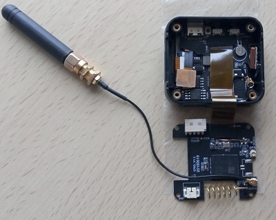
I have LMIC which runs entirely inside the S76G-based T-Watch daughterboard (on it’s STM32L073 MCU) as a part of my SoftRF port on STM32 platform.
But this topic is out of scopes for this ESP32 thread.

t-watch-extant-3

1 Like

Great! Can you share your LMIC port? In your github repo i found binaries only.

The LMIC is integrated into SoftRF as one library of many.
Direct link onto the library is below:

SoftRF/S76G is to be built with Arduino Core STM32 for Nucleo L073RZ target.

Build instructions

3 Likes

This means your whole application, including LMIC, is running on the daughterboard of T-Watch, i guess?

I’m looking for a solution which emulates a native SX1276 on the S76g, thus the S76g is controllable like a RFM95 module.

I’m having problems with my recendly purcharsed board - its exact name is:
SX1276 V2 Lora ESP32 LX6 Dual-Core 0,96" OLED Bluetooth LE Wifi Kit 32 Modul CP2012 IOT 868-915MHz

EDIT: from Heltec
I’ve tried ttn-abp.ino for activating with differend pin settings and i’m never receiving anything in the Data Console … :frowning:
I’ve set up anything properly in my Account with ABP as activation method.

I think for V2 this should be correct:

const lmic_pinmap lmic_pins = {
.nss = 18,
.rxtx = LMIC_UNUSED_PIN,
.rst = 14,
.dio = {/dio0/ 26, /dio1/ 35, /dio2/ 34 }
};

Could it be that I’m already having V2.1 and it requires different settings? (It has only printed “V2” on it)

In my Serial Monitor I’m having something like this:

14:14:02.410 -> Starting
14:14:02.410 -> RXMODE_RSSI
14:14:02.410 -> 9585: engineUpdate, opmode=0x808
14:14:02.410 -> 9618: EV_TXSTART
14:14:02.444 -> 9686: TXMODE, freq=903900000, len=26, SF=7, BW=125, CR=4/5, IH=0
14:14:02.444 -> Packet queued
14:14:03.458 -> 75200: setupRx1 txrxFlags 00 --> 01
14:14:03.492 -> start single rx: now-rxtime: 4
14:14:03.492 -> 75331: RXMODE_SINGLE, freq=923300000, SF=7, BW=500, CR=4/5, IH=0
14:14:03.492 -> rxtimeout: entry: 76664 rxtime: 75325 entry-rxtime: 1339 now-entry: 4 rxtime-txend: 61775
14:14:04.492 -> 138172: setupRx2 txrxFlags 0x1 --> 02
14:14:04.492 -> start single rx: now-rxtime: 4
14:14:04.492 -> 138303: RXMODE_SINGLE, freq=923300000, SF=9, BW=125, CR=4/5, IH=0
14:14:04.526 -> rxtimeout: entry: 140624 rxtime: 138297 entry-rxtime: 2327 now-entry: 4 rxtime-txend: 124747
14:14:04.526 -> 140640: processRx2DnData txrxFlags 0x2 --> 00
14:14:04.526 -> 140700: processDnData_norx txrxFlags 00 --> 20
14:14:04.526 -> 140960: EV_TXCOMPLETE (includes waiting for RX windows)
14:14:04.526 -> 141269: engineUpdate, opmode=0x900

Any ideas what’s wrong?
Thanks

This looks more like some AliExpress product title than the actual make and model of a board.
Start with getting the exact make (manufacturer), model and version of your board first (read the start of this topic for an impression of a subset of available boards).
The board make, model and version are essential for determining:

  • What pin mappings to use
  • If manual wiring of DIO ports is required
  • If additional code is required to get the board running (e.g. like required for TTGO T-Beam V1.0)

Also take care that the TTN LoRaWAN keys/id’s in the sketch are entered correctly and in the correct byte order. See: Format of Keys and ID's for Arduino LMIC libraries [HowTo]

Please read the following for how to format code and logs in your posts:
How do I format my forum post? [HowTo]

2 Likes

Hi,

I have a heltec v1 board, they are not providing the license code so i cannot use the heltec files.
i loaded ttgo file in the heltec that worked well, i see the hello world in hex code in the ttn gateway manager.

the problem i have now is that the rssi is not showing on the display.
i use this code: https://github.com/PiAir/esp32-sx1276/blob/master/TTN_test_ESP32_ABP.ino

any toughts ?

RSSI (received signal strenth indication) is available only for downlink messages.
This could be the reason why you don’t see RSSI on the display.

can i not use the ack for that ?

ACK is received via a downlink message so RSSI should be available when receiving ACK.
The basic Arduino-LMIC examples and your linked code (which is based on ttn-abp.ino) however only print RSSI when data is received in a downlink message (ACK is not data).

To print RSSI when ACK is received but no data is received you will have to modify the code for EV_TXCOMPLETE.

Hi,
i’m having this board: TTGO ESP32-Paxcounter LoRa32 V2.1 1.6 Version 868MHZ
but can’t get it to work (the TTN console won’t receive anything) … here’s my settings:

  • I’m using the MCCI LoRaWAN LMIC Library -> trying to activate via ttn-abp script (yes I think i’ve set up anything properly in my TTN account)
  • modified lmic_project_config.h -> setting the frequency: #define CFG_eu868 1 (also in config.h)
  • in config.h i set the debug level: #define LMIC_DEBUG_LEVEL 2
  • in Arduino IDE: as board I used TTGO LoRa32-OLED V1 (is there a V2.1?)

my ttn-abp script uses the following settings:
NWKSKEY, PROGMEM APPSKEY, DEVADDR <- i’ve pasted it directly from TTN - or do i need to use reverse order? (read it somewhere)

my pin mapping:

const lmic_pinmap lmic_pins = {
    .nss = 18,                       // chip select on feather (rf95module) CS
    .rxtx = LMIC_UNUSED_PIN,
    .rst = 19,                       // reset pin
    .dio = {26, 33, 32}, // assumes external jumpers [feather_lora_jumper]
                                    // DIO1 is on JP1-1: is io1 - we connect to GPO6
                                    // DIO1 is on JP5-3: is D2 - we connect to GPO5
};

^^ there’s a sketch on the Amazon page where i bought it which shows different pins(?)
but I’m not sure how to use them / if they’re correct …

here’s my serial monitor output:

⸮⸮⸮⸮8896
load:0x40080400,len:5816
entry 0x400806ac
Starting
RXMODE_RSSI
9650: engineUpdate, opmode=0x808
9694: EV_TXSTART
9765: TXMODE, freq=867500000, len=26, SF=7, BW=125, CR=4/5, IH=0
Packet queued
75368: setupRx1 txrxFlags 00 --> 01
start single rx: now-rxtime: 3
75500: RXMODE_SINGLE, freq=867500000, SF=7, BW=125, CR=4/5, IH=0
rxtimeout: entry: 77052 rxtime: 75493 entry-rxtime: 1559 now-entry: 4 rxtime-txend: 61863
138252: setupRx2 txrxFlags 0x1 --> 02
start single rx: now-rxtime: 4
138384: RXMODE_SINGLE, freq=869525000, SF=9, BW=125, CR=4/5, IH=0
rxtimeout: entry: 140704 rxtime: 138377 entry-rxtime: 2327 now-entry: 4 rxtime-txend: 124747
140723: processRx2DnData txrxFlags 0x2 --> 00
140768: processDnData_norx txrxFlags 00 --> 20
141023: EV_TXCOMPLETE (includes waiting for RX windows)
141331: engineUpdate, opmode=0x900
3891331: engineUpdate, opmode=0x908
3891355: EV_TXSTART
3891421: TXMODE, freq=867700000, len=26, SF=7, BW=125, CR=4/5, IH=0
Packet queued
3957023: setupRx1 txrxFlags 0x20 --> 01
start single rx: now-rxtime: 3
3957154: RXMODE_SINGLE, freq=867700000, SF=7, BW=125, CR=4/5, IH=0
rxtimeout: entry: 3958707 rxtime: 3957148 entry-rxtime: 1559 now-entry: 4 rxtime-txend: 61863
4019907: setupRx2 txrxFlags 0x1 --> 02
start single rx: now-rxtime: 3
4020038: RXMODE_SINGLE, freq=869525000, SF=9, BW=125, CR=4/5, IH=0
rxtimeout: entry: 4022359 rxtime: 4020032 entry-rxtime: 2327 now-entry: 3 rxtime-txend: 124747
4022378: processRx2DnData txrxFlags 0x2 --> 00
4022438: processDnData_norx txrxFlags 00 --> 20
4022698: EV_TXCOMPLETE (includes waiting for RX windows)
4023013: engineUpdate, opmode=0x900

Any ideas what’s wrong? Thanks

If you see this log, the LMIC stack is sending data, so your pin mapping will be correct and the LoRa radio is working.

You probably did not join the network yet, so check your ABP procedure, esp. the setup for the network.

Any pointers how to modify this code ?
what should i add ?

this original:
case EV_TXCOMPLETE:
Serial.println(F(“EV_TXCOMPLETE (includes waiting for RX windows)”));
u8x8.drawString(0, 5, “EV_TXCOMPLETE”);
digitalWrite(BUILTIN_LED, LOW);
if (LMIC.txrxFlags & TXRX_ACK)
Serial.println(F(“Received ack”));
u8x8.drawString(0, 5, "Received ACK ");
if (LMIC.dataLen) {
Serial.println(F(“Received “));
u8x8.drawString(0, 6, “RX “);
Serial.println(LMIC.dataLen);
u8x8.setCursor(4, 6);
u8x8.printf(”%i bytes”, LMIC.dataLen);
Serial.println(F(” bytes of payload”));
u8x8.setCursor(0, 1);
u8x8.printf(“RSSI %d SNR %.1d”, LMIC.rssi, LMIC.snr);

i changed it into :
case EV_TXCOMPLETE:
u8x8.setCursor(0, 1);
u8x8.printf(“RSSI %d SNR %.1d”, LMIC.rssi, LMIC.snr);
Serial.println(F(“EV_TXCOMPLETE (includes waiting for RX windows)”));
u8x8.drawString(0, 5, “EV_TXCOMPLETE”);
digitalWrite(BUILTIN_LED, LOW);
if (LMIC.txrxFlags & TXRX_ACK)

that did not work :frowning:

My TTGO paxcounter V2.1 finally works - i can confirm these settings (Arduino IDE):
Flashed with board setting “TTGO LoRa 32-OLED V1” (there was no other TTGO Board preset)

const lmic_pinmap lmic_pins = {
    .nss = 18,                       // chip select on feather (rf95module) CS
    .rxtx = LMIC_UNUSED_PIN,
    .rst = 19,                       // reset pin
    .dio = {26, 33, 32}, // assumes external jumpers [feather_lora_jumper]
                                    // DIO1 is on JP1-1: is io1 - we connect to GPO6
                                    // DIO1 is on JP5-3: is D2 - we connect to GPO5
};

I’m now having problems with power supply, when connecting a powerbank (USB) it works like a charm,
but when connecting a Battery to the battery connector there are massive dropouts - see the counter, it should send each 10 seconds:

image

I’m using this battery (which was recommended for the TTGO board) and it should be fully charged:

Is that battery too weak? Any other recommendations?

PS: no success at all with my Heltec V2 - I assume it’s either not the board as expected or it’s damaged … :confused:

To prevent further confusion, that is not the real name of your board.
The correct name of the board is TTGO LoRa32 V2.1-1.6 like shown below.

6

LilyGO is not very consistent in their naming of this board series.
The board’s model name is actually TTGO LoRa32, also referred to as ‘T3’ which is confusing.
V2.1 is the version of the model, while 1.6 is the revision number of this model version. Again confusing due to the double ‘version’ number. ‘TTGO LoRa32 V2.1 rev1.16’ would have been easier to understand.

ESP32-PaxCounter is the name of software that came probably installed on it.
There is a dedicated topic for PaxCounter: Wifi/BLE Paxcounter Project with ESP32 boards