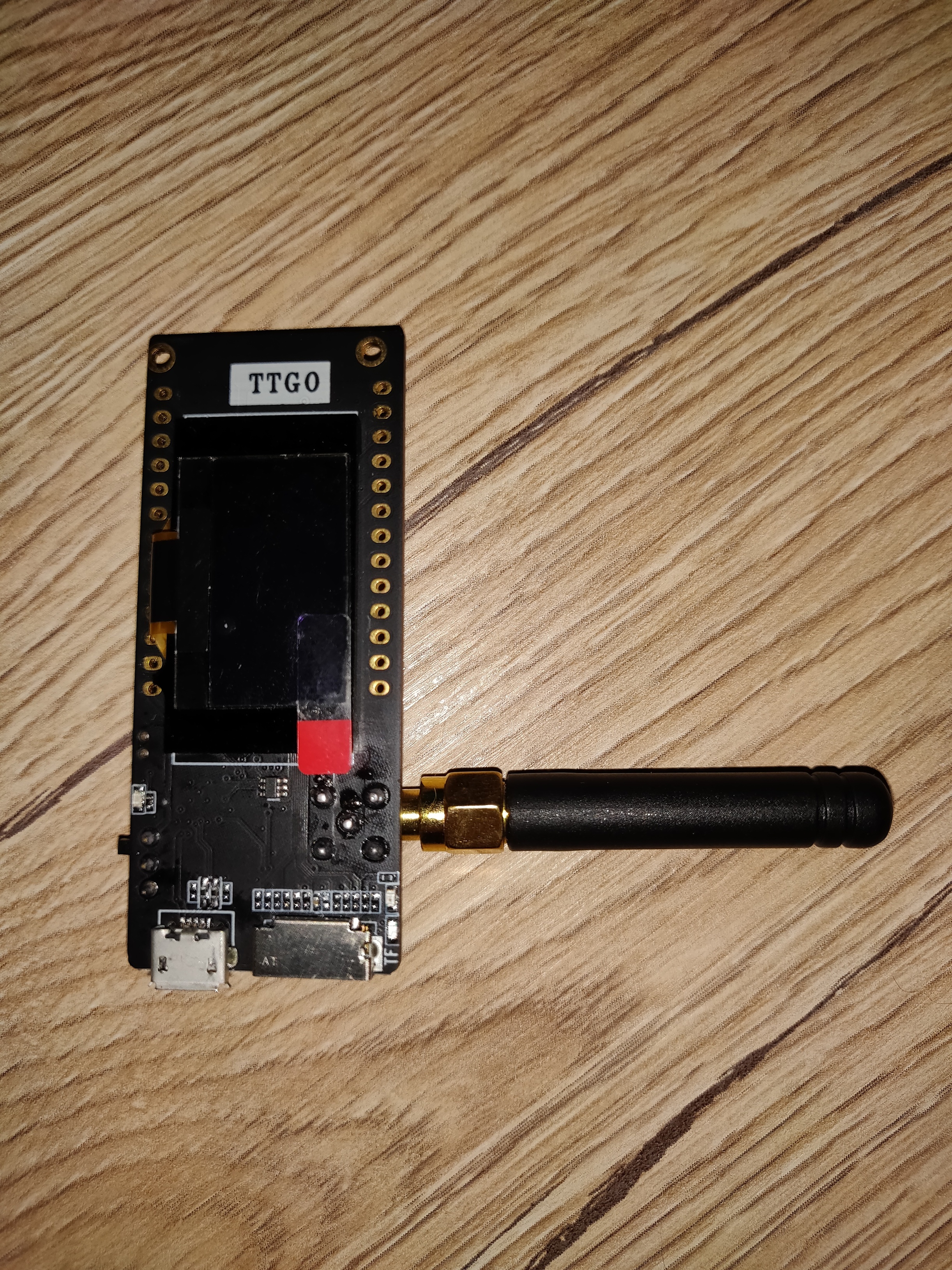
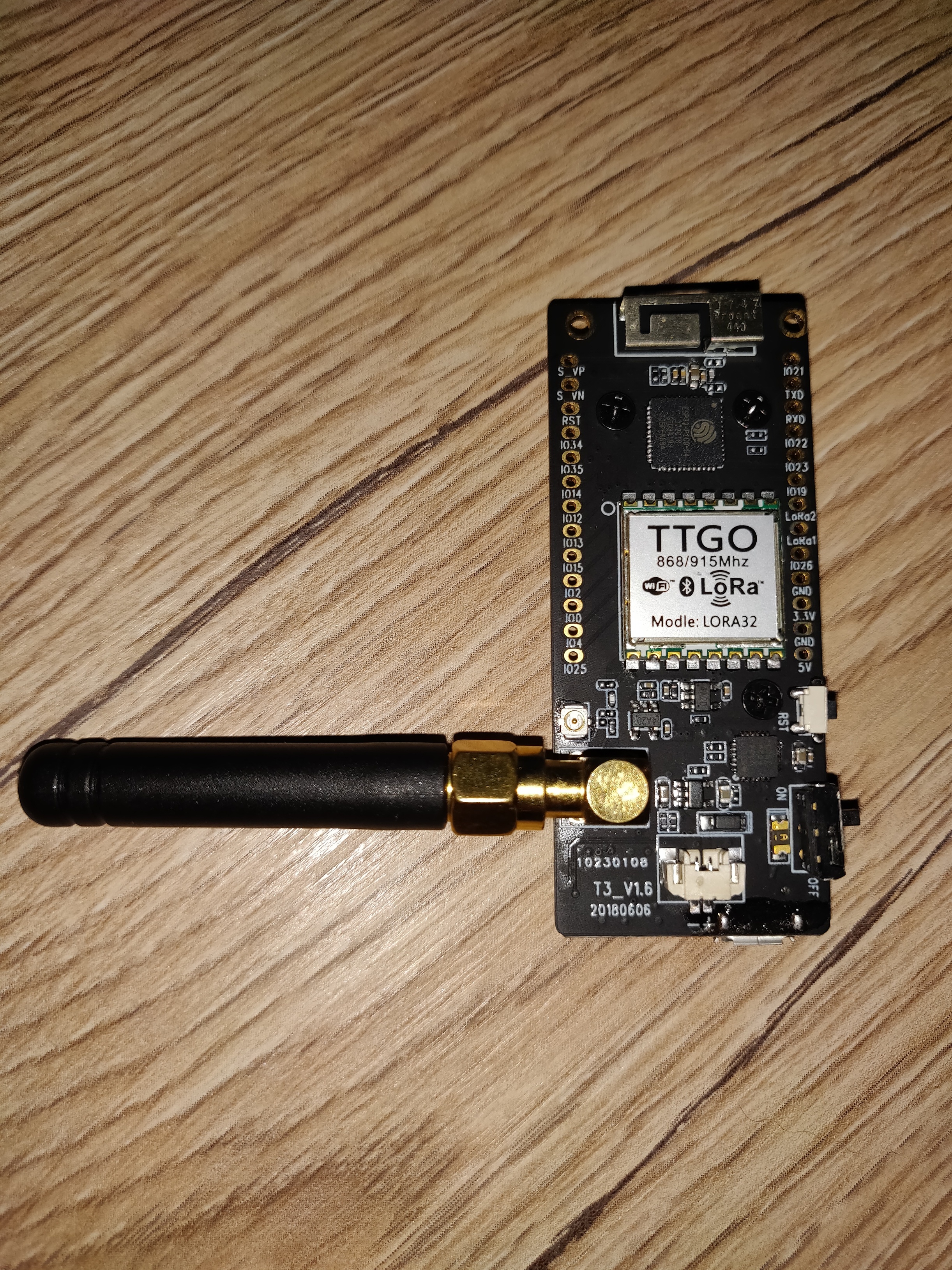
I am trying to get this to work in Riga, Latvia. This is capital city, I checked global gataway map and there are like 5 gateways showing up, moustly universities puting them up, but I do not know how to check if I have good coverage and how many channels are available. Was thinking of changing SF7 to SF9, as I understand that would increase air time but would allow to contact gateways at greater distance, but when I change to SF9 in code and compile/upload it to TTGO node it still shows SF7 on oled screen and in terminal log.
I did check if DIO1 ( labeled Lora1 on ttgo 2.1 1.6 board ) is connected - I checked ttgo pin is connected to lora module pin whth multimeter, but I could not perform continuity check from ttgo lora1 pin to esp32 chip pin as the esp32 pins are too small for my multimeter. BUT i did try to wire ttgo lora1 pin to other pin on ttgo board and use that in configuration, but that did not make any difference, it seemed it made module to not even get to joining OTAA.
Joining always starts with SF7, and over time LMiC increases SF if it cannot join. So just leave the module some hours outside and wait. Maybe you just have a coverage problem. Could therefore be useful to get closer to a gateway for testing.
Using TTGOs with OLED display you need to keep in mind that their display is connected to the i2c bus, too. This is of course not a hardware problem, since i2c has bus device addressing, but can cause a software issue if you try to access OLED and BME from parallel running tasks on a RTOS platform, like ESP32-IDF / arduino-esp32. Concurrent access to i2c bus results in bus errors and may cause the i2c driver stop working. To prevent this you need a mutex mechanism in the software, or you keep i2c bus access in a single task (e.g. loop-task in arduino).
Trying now with default configuration for my module. Waiting patiently for it to manage SF itself. And got some signal in TTN console, the yellow lightning icon one. Here are metadata from it:
Looks like signal is week, if I read this correctly.
{
“time”: “2019-08-08T12:08:38.492242962Z”,
“frequency”: 868.3,
“modulation”: “LORA”,
“data_rate”: “SF10BW125”,
“coding_rate”: “4/5”,
“gateways”: [
{
“gtw_id”: “eui-b827ebfffef8045f”,
“timestamp”: 605165132,
“time”: “”,
“channel”: 1,
“rssi”: -120,
“snr”: -10.8,
“rf_chain”: 1
}
]
}
At -10.8dB SNR, you have around 4dB of link margin to the failure point, so about 60% more distance, all other things being equal.
Console shows the reception level at the gateway’s site. With RSSI -120 your node probably can’t hear the gateway, so cannot process the OTA join answer.
You need to get closer to a gateway.
The gateway’s MAC looks like a raspberry. Many RasPis are operated indoor. Try to find an outdoor gateway.
Hi,
I acquired a board TTGO ESP32. I get connected to my network. But when I configured in TTN. I get error not connected. What is the problem?
SPIFFS loaded success
Assert=Do Asserts
debug=1
readConfig:: Starting
SSID=ONOF6A5
CH=0
SF =7
FCNT=0
DEBUG=0
CAD=0
HOP=0
NODE=0
BOOTS=19
RESETS=0
WIFIS=19
VIEWS=0
REFR=0
REENTS=0
NTPETIM=0
NTPERR=0
NTPS=18
MAC: 00:a0:00:61:00:7c, len=17
0:1. WiFi connect to: ONOF6A5
WLAN reconnected
Hi there,
I also Just bought a ttgo lora32 OLED and got the 2.1 1.6 Version. I tried to load several sketches and followed different Tutorials, but none of them resulted in an incoming Data on the ttn console. Coverage should not bei the issue, as I’m running a dragino next to it, which is conncted to ttn.
In the sketches I tried to Set Up the pinmap according different Tutorials, i set the rf ftequency to EU in the lmic Project config and I inserted the id’s in lsb and msb according to tutorials. Nothing worked.
AFAIK no manual wiring is needed on the board, right?
Can, please, someone provider a working example Sketch for the ttgo 2.1 1.6 board?
Thanks in advance
BR Harald

Dragino is a single channel gateway, so it’s not LORAWAN compliant. LMiC won’t work without special patches. Better go for a compliant 8ch gateway, e.g. TTIG which has nearly same pricing as dragino.
what gateway do you use and is it connected and working on TTN ?
did you add an application and add this node ?
what software have you loaded on the node ?
Thanks for your answer. In my are there should be several other gateways (not owned by my), according to ttnmapper. Do you maybe have a working example for this board?
As these are my first steps with lora it is difficult to debug this problem, and it would be awesome to have known working example sketch to exclude this as an error source…
Use Paxcounter software, it supports different boards and is proven to work.
Hi ClimberWue, and thanks for the reply. I used the OLED I2C bus without being able to connect the BME280, no problem found with other types of I2C sensors. To dispel any doubt I used more than one BME280. in any case, no alternative I2C bus is available on the TTGO LoRa v2.0. If you have other suggestion please let me know.
Hi Paul and thank you for your valuable answer. I tried using Wire.begin(21,22) as you suggested, without any success… The BME280s don’t work unlike the other I2C sensors I have. Would you have a working sketch that uses a BME280 with a TTGO LORA32 v2.0? It would be really useful, maybe it’s a problem related to a library that I use, even if it’s rather strange, since I have never had these problems with the BME280. Thanks again for your help!
Questions:
- Which board have you selected in the IDE?
- Which library are you using for BME280?
- How have you initialized the library?
Possible cause:
- Using a board definition that does not define the correct default pins for SDA and SCL.
Possible solutions:
- Use a board definition that defines the SDA and SCL pins correctly.
- Call Wire.begin(21, 22) before calling any sensor’s begin().
- Use a different bme280 library.
Another option is to put the BME on a separate I2C bus. If you do not have a spare hardware I2c bus then you can use a software I2C such as SoftwareWire.
That would be useful (only) if GPIO pins used for display I2C are not available as physical pins on the board (and SCL and SDA as defined by the board definition would point to GPIOs used for display I2C).
TGO LoRa32 v2.0 uses GPIO 21 for SDA and 22 for SCL. Used by display and also available as external pins. Sharing I2C by display and sensors should normally not cause problems.
After further investigation I found that ESP32 Wire.begin() will remember it’s initial values.
So after an initial call like Wire.begin(23, 25) where custom I2C pins are set, any subsequent call to Wire.begin() but without parameters (like some libraries do) will not cause the I2C interface to be reset to its default pins (21 and 22 on TTGO LoRa32 v2.0).
The following board definitions do provide the correct I2C pin definitions:
ttgo-lora32-v1
heltec_wifi_lora_32
heltec_wifi_lora_32_V2
For a TTGO LoRa32 v2.0, board definition ‘TTGO LoRa32 V1’ will match best
(but for a v2.0 board the definition of LED_BUILTIN and LORA_RST will be incorrect).
This is the only TTGO LoRa32 board definition that is currently available.
I am not sure what you mean. Based on his comments in previous posts he appears to be dealing with several possible problems:
-
The CSB pin on the BME280 is floating with can cause the BME280 to switch at ant time to SPI mode. Once in SPI mode a power-on-reset is required to get it back to I2C mode
-
I2C bus termination problem. If sometimes the BME devices are not seen during discovery it could be because the I2C pull-ups are missing or not soldered correctly
-
I2C bus loading problem. Similar to the previous problem but in this case the combined effective load resistors are too low in value.
-
There is address conflict on the I2C bus
-
I2C device driver contention problems
-
BME driver software. I see you already called out the I2C begin problem. It has a similar problem with SPI. If you have a target that does not use SPI and you set the SPI interfaces to 0 in the variant.h file, a subsequent compile that includes the driver even if you only want to use I2C will fail.
Other than 1 and possibly 2 above, all other scenarios can be addressed using a software I2C bus.
Another option is to put the BME on a separate I2C bus
That would be useful (only) if GPIO pins used for display I2C are not available as physical pins on the board (and SCL and SDA as defined by the board definition would point to GPIOs used for display I2C).
I am not sure what you mean. Based on his comments in previous posts he appears to be dealing with several possible problems:
What I meant is that only in case the display’s I2C pins would be wired to GPIO ports that are not available externally as physical pins on the board, would there be a need to use a second I2C interface for the BME280 (on different pins).
But his board is a TTGO LoRa32 v2.0 so the standard I2C pins are available and are the same as used by the display.
The OLED display and sensors should be able to share that same I2C interface.
An I2C address conflict is less likely because display and sensors are different categories that use different I2C address ranges.
The ESP32 supports 2 hardware I2C interfaces so there is no need to use a ‘software I2C bus’.
no alternative I2C bus is available on the TTGO LoRa v2.0
It is possible to use a second I2C interface on the ESP32.
But I suspect that that is not the cause of / will not fix your problem.