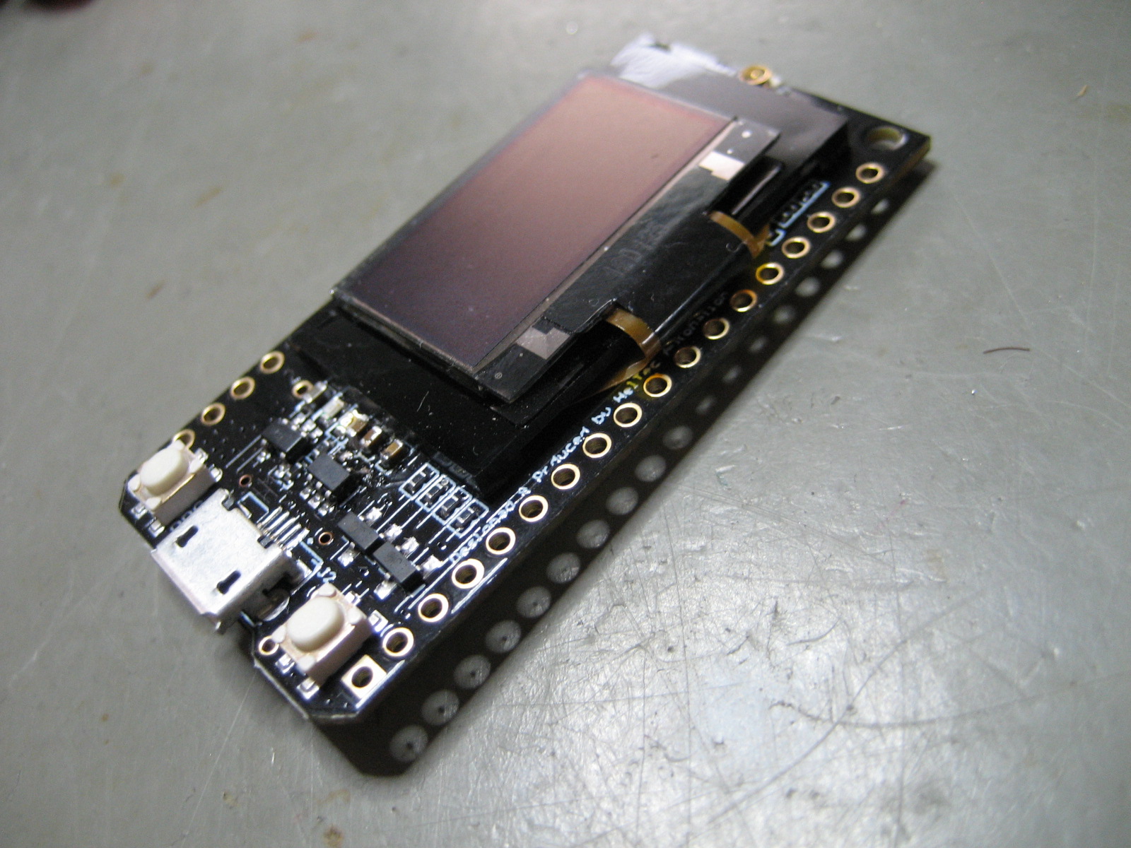
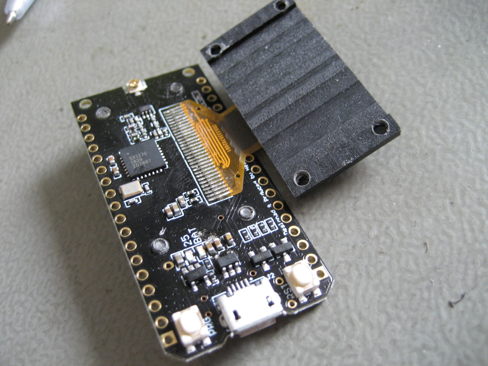
Looks like the pads for the oled display.

It’s a printed on board capacitor acting as backup power source 
thank you for your answers
It looks more like a touch slider control for adjusting the RF power. ![]()
![]()
I have a TTgo V1 that the microUSB port has come off.
The fine pins are beyond my soldering capabilities, so is there any other way to communicate with the board eg through the RX/TX pins?
Cheers
Paul
Yes, it should be possible. According to the schematics, the RX/TX pins are connected to a CP2102 USB-UART bridge controller. If you have USB-UART module like this below you can connect to the ESP32.
Thanks, have since confirmed you can do it
For future reference of others, using RX, TX, GND and 3v3.
When using in Arduino, hit the upload button and wait till it compiles and starts to try and find a serial port, then hold down program, press reset briefly then let go of program.
Then the sketch should start uploading
Cheers
Paul
Yes thanks, that is how a sketch should be ‘manually’ uploaded to the ESP32.
(The same sequence is used for the ESP8266.)
Almost any (breadboard-friendly) ESP32 board already has a USB to Serial adapter integrated on the board so most users never have to press the program and reset buttons sequence (not know about it).
(The integrated onboard USB to Serial adapter uses two transistors in combination with DTR and RTS signals to make uploading go automatically without having to press any buttons.)
Be aware of the 3.3V: When using the separate USB to Serial adapter with your ESP32 board never connect two power sources to the board at the same time. If the board is already powered by a different power source (e.g. a battery or power supply connected to a breadboard) then you should NOT connect the 3.3V power line from the USB to Serial adapter to the board at the same time.
(When normally using the USB connector to both power and program the board this is less/not an issue because power from the USB is normally protected with a diode that prevents reverse currents to the USB port if you have also powered it on the 3.3V pin. But when you power it via the USB to Serial adapter that security measure is not present.)
(Also note that certain CP2102 based boards have a bug where they can output near 5V instead of 3.3V (on the 3.3V line). There also exist CH340 based USB to Serial adapters that you can switch between 5V and 3.3V output but (totally unexpected!) the Rx and Tx signals levels always stay at 5V.
To prevent possibly damage, it is best to measure the output supply voltage(s) and signal level voltages of your (Chinese) USB to Serial adapter before blindly trusting it’s advertised specifications.)
New Heltec v2, running the Paxcounter software
Strange I just received this board and not receiving a EV_TXCOMPLETE event. As if DIO’s were not connected correctly. Could also be a bad board … which would simply be bad luck ![]()
Hi maybe there different boards out threre? I found an Answer that made my TX complete on the git, See below. Greetings from Vienna to Verkehrsrot who is doing a great Job!
ssozonoff commented 4 days ago
Had to change as follows in heltecv2.h file else you wont get a complete event for the lora sends.
#define LORA_IRQ 26
#define LORA_IO1 35
#define LORA_IO2 34
There was a bug in paxcounter software, pin mappings of v1 were used on v2. I fixed this today.
Hi All,
I am using a TTGo V2 as a base for a tank and cattle trough sensor using a pressure transducer.
I would like to send the TTGo to sleep in between readings to save power, and have been able to achieve this fairly simply.
The issue is that when it wakes up it has to rejoin the network every time from scratch.
Would anybody be able to share a sketch that stores your OTAA session keys before sending to sleep so that it doesn’t have to rejoin every time it starts up.
cheers
Paul
what do you mean by ’ have been able to achieve this fairly simply.’… shutting down power completely ?
Just by using the ESP32 Timer Deep sleep example
Specifically
esp_sleep_enable_timer_wakeup(TIME_TO_SLEEP * uS_TO_S_FACTOR);
and using this line after a TX Complete
esp_deep_sleep_start();
regards
Paul
edit: I am guessing the answer might be in using some of this but its a bit beyond my coding experience.
Thank you so much man !
Saved me
Hallo,
second: My Problem: No EV_TXCOMPLETE occurs.
Board TTGO V2.1 1.6
Connection OTAA
Pin mapping:
lmic_pinmap lmic_pins = {
.nss = 18,
.rxtx = LMIC_UNUSED_PIN,
.rst = 12, //12?
.dio = {26, 33, 32},
};
Arduino IDE LMIC https://github.com/matthijskooijman/arduino-lmic
with #include <hardwareSerial.h>
#include <lmic.h>
#include <hal/hal.h>
#include <SPI.h>
Programm based on the example OTAA in the library
Package arrived in the Application and is decodet, but no EV_TXCOMPLETE occurs.
Had someone any idea?
Greetings Ernst
first :you can… now ![]() (but this is the right topic and your question is in english)
(but this is the right topic and your question is in english)
what gateway do you use ?
My Gateway is a Raspberry Pi with IMST ic880A-Board.


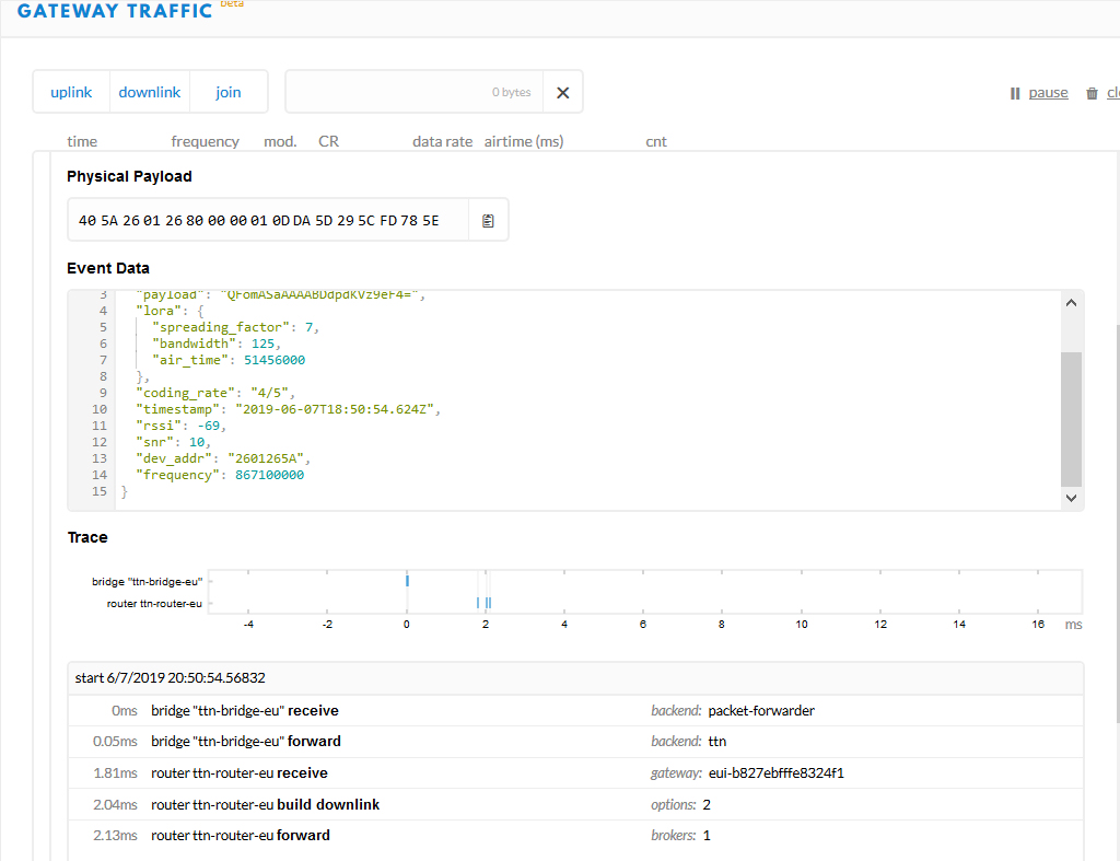
looks that on your gateway side everything is ok 
the OTAA node joins So it must be related to your code / board
maybe a timing issue, the node won’t receive the otaa join
I’m not a specialist … but adding to this line your code ? it increases the receiving window a little bit
LMIC_setClockError(MAX_CLOCK_ERROR * 1 / 100
Thanks for the tip, I tried it, but unfortunately without any success.
Greetings
Ernst