Big ESP32 + SX127x topic part 2

For LMIC-Arduino use the following formats:

// For activation type OTAA (over the air activation) use:

// DevEUI (end-device identifier) in LSB (least-significant-byte) first / little endian format.
static const u1_t PROGMEM DEVEUI[8] = { 0x00, 0x00, 0x00, 0x00, 0x00, 0x00, 0x00, 0x00 };

// AppEUI (application identifier) in LSB (least-significant-byte) first / little-endian format.
// For TTN issued EUIs the last bytes should be 0xD5, 0xB3, 0x70.
static const u1_t PROGMEM APPEUI[8] = { 0x00, 0x00, 0x00, 0x00, 0x00, 0x00, 0x00, 0x00 };

// AppKey (application key) in MSB (most-significant-byte) first / big endian format.
static const u1_t PROGMEM APPKEY[16] = { 0x00, 0x00, 0x00, 0x00, 0x00, 0x00, 0x00, 0x00, 0x00, 0x00, 0x00, 0x00, 0x00, 0x00, 0x00, 0x00 };

// For activation type ABP (activation by personalization) use:

// DevAddr (end-device address) in MSB (most-significant-byte) first / big endian format.
// Note that in the example it is defined as u4_t, not as an array of u1_t.
static const u4_t DEVADDR = 0x00000000 ;

// NwkSKey (network session key) in MSB (most-significant-byte) first / big endian format.
static const PROGMEM u1_t NWKSKEY[16] = { 0x00, 0x00, 0x00, 0x00, 0x00, 0x00, 0x00, 0x00, 0x00, 0x00, 0x00, 0x00, 0x00, 0x00, 0x00, 0x00 };
// AppSKey (application session key) in MSB (most-significant-byte) first / big endian format.
static const u1_t PROGMEM APPSKEY[16] = { 0x00, 0x00, 0x00, 0x00, 0x00, 0x00, 0x00, 0x00, 0x00, 0x00, 0x00, 0x00, 0x00, 0x00, 0x00, 0x00 };
1 Like

Thanks bluejedi,

So for ABP, DevAddr can be copied just as it is listed in Hex format. In a post I read it should be LSB, so currently I reversed the bytes in the sketchā€¦ The 2 other keys are shown initially as MSB, so those I should have correct.

Yes, DevAddr must be in MSB and can be copied as shown by default in the console (it is not defined as an array in the LMIC code example so no need to select the array format in the console).

Thanks, in that case Iā€™ll have to revert my change and put in the proper DevAddrr. I also got message from the gateway owner that both MSB and LSB keys are supported, as long as they exist in my Application.

Currently Iā€™ve put my Heltex card next to a window, hoping that it can pickup the gatewayā€™s signalā€¦

Also, should I specify the Handler (set to ttn-handler-eu)?

Different keys / IDs can be defined in different byte orders in the source code, as in the case of OTAA.
However, there is no such thing as a MSB and LSB version of the same key / ID and that these are both supported on the gateway. There exists only one value of a key.

The LoRaWAN protocol defines in what byte order the keys and IDs must be transferred over the air, but in the source code for the definition of a key or ID a different byte order may be used. Therefore define keys and IDs in the byte order how they are used in the source code. For LMIC-Arduino the byte orders of the different keys and IDs are defined in the LMIC-Arduino library code.

A different LoRaWAN stack/library can possibly require different byte orders than LMIC-Arduino.

Yes, in Application settings.

In any case, the keys should be in the proper byte order. And Iā€™ve opened the window and put the (default short) antenna outsideā€¦ Still no data arriving in my application. So if all seems to be set properly, the only conclusion I can make is that Iā€™m still not in reach of a gatewayā€¦

(using the Arduino LMIC Master library)

Ok, Iā€™ve just order another 868 antenna to replace the ootb small antenna that came with my Heltec boardā€¦ If that doesnā€™t workā€¦ :scream:

1 Like

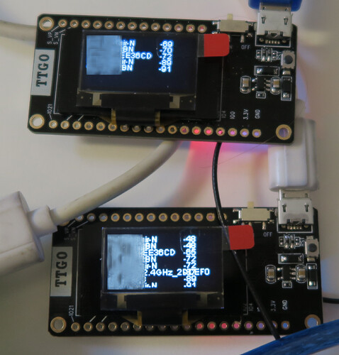
Today i received another TTGOv2, ordered on Aliexpress.

Shipping option ā€œAli Express Standardā€ took longer than ā€œePacketā€. I ordered on 25/01, the package arrived 19/02, so this makes ~25 days from China to Germany. The other one ordered with option ā€œePacketā€ took 15 days. Both not too bad for free shipping.

But now to the downsights:The OLED-Display arrived broken, the right part shows pixel garbage, even in the original flashed demo application. So those chinese quality issues seem to continue with TTGOv2.

Enough time waste for me. I switched to Pycom LoPy, also ESP32 based, and similar features, but no display of course.

Another point: I tried to operate the board in original shape, without external wiring of DIO1. As expected this causes missing LMIC events TX_complete. So the TTGOv2 is unusable for LMIC without extra wiring.

Since i assume that no one needs the micro sd card reader, the one and only advantage of TTGOv2 compared with Heltec is the proven better Wifi antenna.

Heltec announced a new board v2 for march 2018. Letā€™s wait and seeā€¦

Not shure about that. Have a pair since a few weeks. And they differs much in wifi RX.


Cannot find any optical issue or difference on the antennas.

The on board so called ā€œ3Dā€ wifi antennas on the TTGOv2 are much better than the coil antennas on the Heltec boards. I proved that by counting seen MAC frames in monitor mode over a full week, the difference in total count was signifcant compared with the Heltec. But the performance is still poor compared with the onboard taoglass ceramic antenna on the LoPy/LoPy4.

I have not seen any hard figures yet but my expectation is that LoRa performance of TTGO V2 will be substantially better than the Heltec and the other TTGOā€™s boards due to use of the HPDTek LoRa module.

Donā€™t focus too much on the included antenna, get something better or tune it somehow and take care of a proper groundplane.
Even the antenna included with the RAK831 gateway board is sub-optimal (understatement).

:cry::cry::cry::cry:

Hi, I just joined to add a comment asā€¦

a. I have just got a pair of TTGO boards in the post to play with
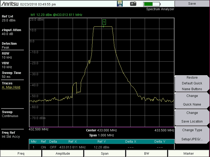
b. Iā€™m struggling to get more that around 12dBm out of the boards (they claim 20dBm)

I havenā€™t looked to see if there is some soldering fault yet, but the two boards have remarkably similar outputs (within 0.1 dBm), so it seem unlikely they are both identically faulty.

What I have done so far is to load up the OLED_LoRa_Sender and receiver code from the Heltec git page (https://github.com/Heltec-Aaron-Lee/WiFi_Kit_series). I then ran the Tx code on both boards, and fed the output into my Anritsu spectrum analyser to see how the output looked (Image hopefully attached)

The measurements showed a pretty consistent 12.2 dBm output across the expected ~125kHz bandwidth, but what ever I try with the the PA pin settings and TxPower, I donā€™t get any higher Tx output.

My previous experiments with a couple of RA-01 modules gave me ~18dBm, and this gave me a range of around 5-6 Km without too much messing about. I havenā€™t had the chance to test the range on these yet, but Iā€™m not expecting > 1-2 km at these power levels.

Has anyone done any tx power tests on these? And and I missing something obvious on the PA/Power config?

Might be time to order a couple of v2 boards and see how they behave, although it sounds like the main change between v1 and v2 is the wifi performance, which Iā€™m not really worried about right nowā€¦

lora oled tx17

Ok, yesterday I decided to do a sort of wardriving after work on my way home to see if my Heltec is actually sending out a signal. Driving near one gateway location resulted in 14 Frame Upsā€¦ but no data in my console. So, it definitely has to do with signal coverage. Iā€™m using a proper 868 MHz antenna. Does anyone know

  1. how to ā€œtune the spreading factorā€ or ā€œincrease the tx powerā€?
  2. Why I donā€™t see any data in my ttn console while there are 14 Frame Ups? If it is due to missing or incomplete payload decoder/converter, can someone provide an example for both the ttn_abp.ino and the ttn_otaa.ino examples?

Thanks again.

Ok, kit is now outside on a table andā€¦ tadaaaā€¦ Iā€™m receiving data on my TTN console.

But maybe one of you more experienced IoT gurus can create a full workshop around the ttn_abp/ttn_otaa examples including a Payload Converter/decoder or whatever to complete the example exercise.

Regs, Jean-Pierre

1 Like

Good to hear that you succeeded in getting it to work.

It would indeed be nice to have some complete walk-throughā€™s. But at least the basic steps are already provided in this topicā€™s start (but without the payload stuff): which libraries, which settings and which sketch to use for getting a basic node up and running.

The TTGO boards use SX1276 chip, this has different RF output pins: RFO_HF/LF (depending on frequency band) and PA_Boost.

In the LMIC code power switching between this pin is done in radio.c, the part of code looks like this (note- i tweaked it a little):

static void configPower () {
#ifdef CFG_sx1276_radio
    // no boost used for now
    s1_t pw = (s1_t)LMIC.txpow;
    if(pw > 15) {
        pw = 15;
    } else if(pw < 2) {
        pw = 2;
    }
    // check board type for BOOST pin
    writeReg(RegPaConfig, (u1_t)(0x80|(pw&0xf))); // sets PA_BOOST pin (original lmic)
    //writeReg(RegPaConfig, (u1_t)(pw&0xf)); // sets RFO pin (patched lmic)
    writeReg(RegPaDac, readReg(RegPaDac)|0x4); 

Original LMIC uses PA_BOOST pin. I tried to switch to RFO_HF pin. This caused on the TTGOv2 module that there was no RF power at all, or to be more precise, because i do not own a spectrum analyser: no packets at all seen on the gateway.

Unfortunately we donā€™t know the schematic of the TTGOv2 board here, but i assume RF power is taken from PA_BOOST pin only. So, this way it should be possible to reach the 20dB output power from the SX1276 when switching it in the PA_BOOST and maxium TX power mode. If the 20dB then do not show up at the antenna of the board, it means the board has bad RF output path.

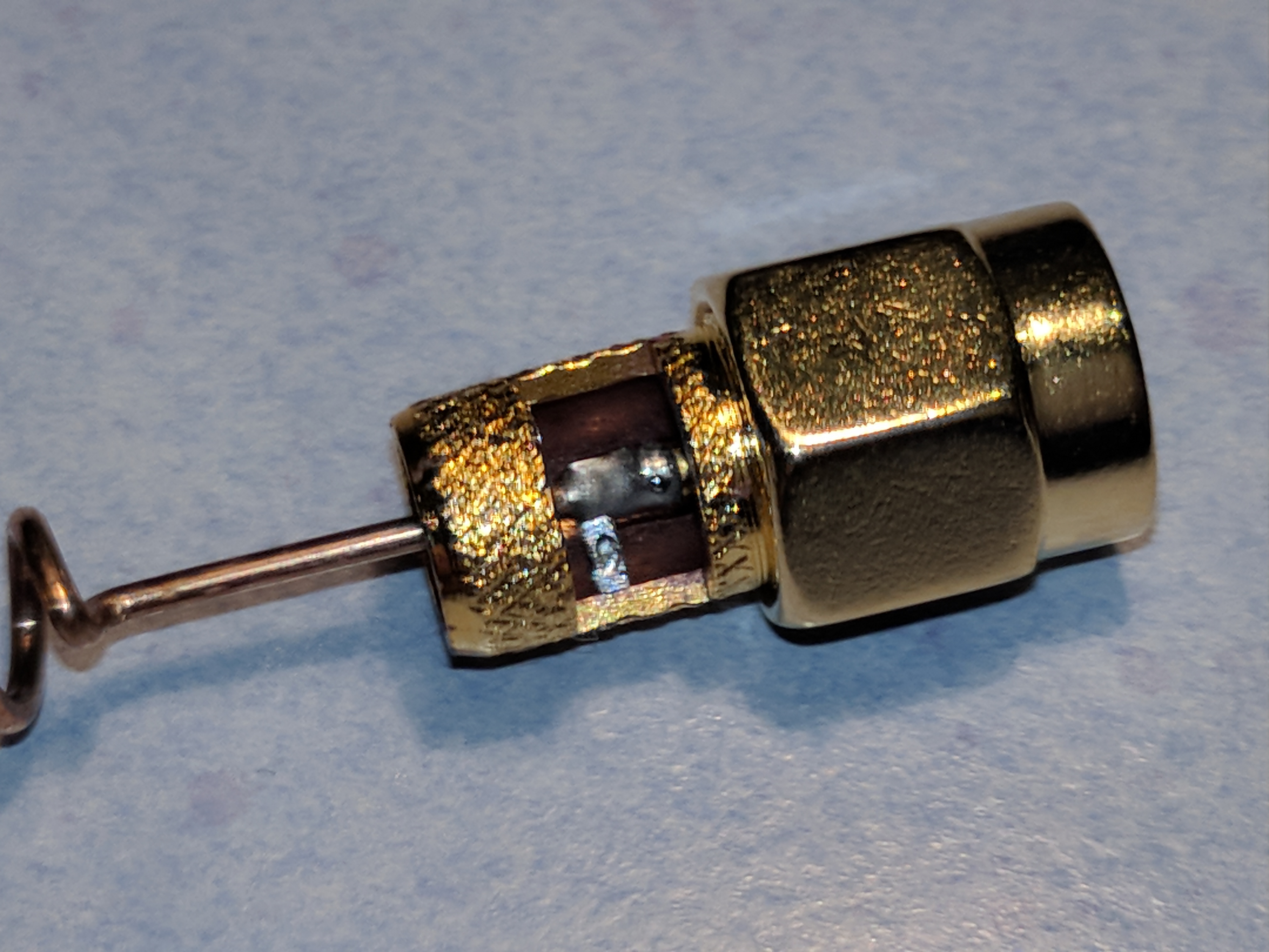
I opened two antennas which came with the Heltec and TTGOv2 boards.

They are not identical, the length of the coils is slightly different.
One has a short cut caused by a loose piece of solder in the SMA plug (see picture).

So it maybe useful to examine those antennas before use. The plastic cap can easily be removed and reattached to the SMA plug, itā€™s not glued.

IMG_20180224_181000

IMG_20180224_180816

2 Likes

I found the coils to be (nearly) identical: The BIG and SMALL ANTENNA topic part 1
It is the antenna length below the coil that is different. I measured a difference of two millimeter. On the picture the difference between your antennas appears even more.

Goodmorning everyone
I successfully managed to run my ESP32 Heltec with the LMIC-Arduino library
can be found here: https://github.com/matthijskooijman/arduino-lmic .

After setting the keys for ABP in the sample file ttn-abp.ino ,
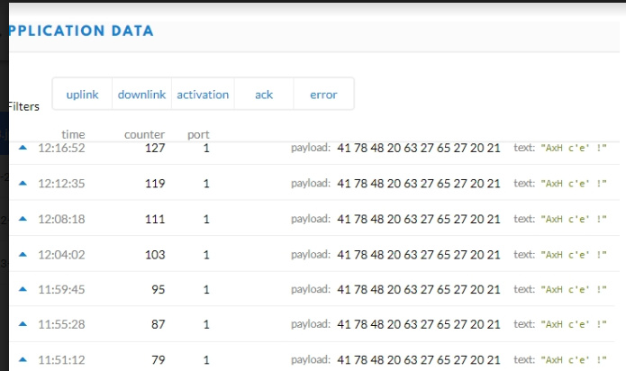
on the gateway I receive the messages, but they are not comtinues,
in TTN console application I receive data every 8 frames

Output example
image

Is there a setting to be modified to be able to send all frames, in sequence?
thanks

Hello All !
jpg_640x640

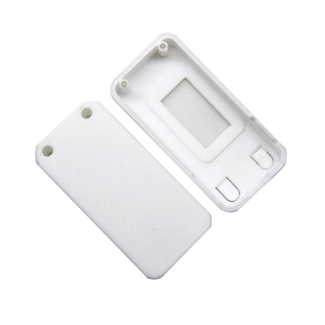
if you have 3d printer, you can print shell for TTGO ESP32 LORA.
liligo send me this (printed version canā€™t buy now :frowning: )
https://goo.gl/CyRpNz